
Reference Guide


232 | Uplink Failure Detection (UFD)
www.dell.com | support.dell.com
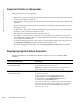
Important Points to Remember
UFD operates as follows on an Aggregator:
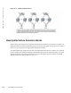
• Uplink-state group 1 is created by default with the uplink LAG 128 as the upstream interface and all
server ports as downstream interfaces.
When the uplink LAG goes down, all server interfaces are brought down and placed in UFD error-dis-
abled state.
When the uplink LAG comes up again, server interfaces are brought up (Oper UP) and the error-dis-
abled state is cleared.
• A defer timer of 10 seconds is enabled in the uplink-state group. This defer timer prevents unwanted
flapping of server ports when the uplink LAG flaps.
The defer timer is also helpful in scenarios similar to this one:
The uplink LAG consists of ports connected to two ToR switches. The currently active LAG goes
down. Without the defer timer, the server ports would be shut down before even trying to bring up the
LAG with the second ToR switch.
• To enable the debug messages for events related to a specified uplink-state group or all groups, enter
the
debug uplink-state-group [group-id] command, where group-id is 1 to 16.
To turn off debugging event messages, enter the
no debug uplink-state-group [group-id] command.
Displaying Uplink Failure Detection
To display information on the Uplink Failure Detection feature, enter any of the following show
commands:
Show Command Syntax Description
show uplink-state-group [group-id] [detail]
Command Mode: EXEC
Displays status information on a specified uplink-state group or all
groups. Valid group-id values are 1 to 16.
detail displays additional status information on the upstream and
downstream interfaces in each group (see Figure 20-3).
show interfaces interface
Command Mode: EXEC
Displays the current status of a port or port-channel interface assigned
to an uplink-state group.
interface specifies one of the following interface types:
10-Gigabit Ethernet: Enter tengigabitethernet slot/port.
40-Gigabit Ethernet: Enter fortygigabitethernet slot/port.
Port channel: Enter port-channel {1-512}.
If a downstream interface in an uplink-state group has been disabled
(Oper Down state) by uplink-state tracking because an upstream port
went down, the message error-disabled[UFD] is displayed in the
output (see Figure 20-4).