
Owner's Manual


Setting Up an iSCSI Cluster 37
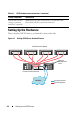
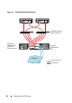
To configure your nodes in a switched configuration, see Figure 4-2.
1
Connect one CAT 5e/6 cable from a port (iSCSI HBA or NIC) of node 1 to
the port of network switch 1.
2
Connect one CAT 5e/6 cable from a port (iSCSI HBA or NIC) of node 1 to
the port of network switch 2.
3
Connect one CAT 5e/6 cable from a port (iSCSI HBA or NIC) of node 2 to
the port of network switch 1.
4
Connect one CAT 5e/6 cable from a port (iSCSI HBA or NIC) of node 2 to
the port of network switch 2.
5
Connect two CAT 5e/6 cables from switch 1 to the
In-0
port of RAID
controller 0 in the PowerVault MD32
xx
i storage enclosure.
6
Connect two CAT 5e/6 cables from two other ports of switch 1 to the
RAID controller 1 in the PowerVault MD32
xx
i storage enclosure.
7
Connect two CAT 5e/6 cables from a port of switch 2 to the RAID
controller 0 in the PowerVault MD32
xx
i storage enclosure.
8
Connect two CAT 5e/6 cables from two other ports of switch 2 to the
RAID controller 1 in the PowerVault MD32
xx
i storage enclosure.
9
If applicable, connect two SAS cables from the two PowerVault MD32
xx
i
storage enclosures
Out
ports to the two
In
ports of the first PowerVault
MD12
xx
expansion enclosure.
10
If applicable, connect two SAS cables from the two PowerVault MD32
xx
storage enclosures
Out
ports to the
In
ports of the second PowerVault
MD12
xx
expansion enclosure.
NOTE: For information on configuring the PowerVault MD12
xx
expansion
enclosure, see the PowerVault MD32
xx
i storage system documentation at
suport.dell.com/manuals
. It is recommended to use a separate network for the
iSCSI storage infrastructure. If a separate network cannot be dedicated for iSCSI,
assign the storage function to a separate virtual local area network (VLAN); this
action creates independent logical networks within a physical network.