
Owner's Manual


Setting Up an iSCSI Cluster 35
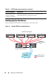
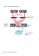
To configure your nodes in a direct-attached configuration, see Figure 4-1.
1
Connect one CAT 5e/6 cable from a port (iSCSI HBA or NIC) of node 1
to the
In-0
port of RAID controller 0 in the PowerVault MD32
xx
i
storage enclosure.
2
Connect one CAT 5e/6 cable from the other port (iSCSI HBA or NIC) of
node 1 to the
In-0
port of RAID controller 1 in the PowerVault MD32
xx
i
storage enclosure.
3
Connect one CAT 5e/6 cable from a port (iSCSI HBA or NIC) of node 2
to the
In-1
port of RAID controller 0 in the PowerVault MD32
xx
i
storage enclosure.
4
Connect one CAT 5e/6 cable from the other port (iSCSI HBA or NIC) of
node 2 to the
In-1
port of RAID controller 1 in the PowerVault MD32
xx
i
storage enclosure.
5
Repeat step 1 to step 4 for node 3 and node 4 to connect to In-2 and In-3
of RAID controller 0 and RAID controller 1.
6
If applicable, connect two SAS cables from the two PowerVault MD32
xx
i
storage enclosures
Out
ports to the two In ports of the first PowerVault
MD12
xx
expansion enclosure.
7
If applicable, connect two SAS cables from the two PowerVault MD12
xx
storage enclosures
Out
ports to the
In
ports of the second MD12
xx
expansion enclosure.
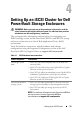
NOTE: For information on configuring the PowerVault MD12
xx
expansion
enclosure, see the PowerVault MD32
xx
i storage system documentation at
support.dell.com/manuals
.
Switched iSCSI clusters can support up to thirty two nodes.