
Owner's Manual


42 Setting Up an iSCSI Cluster
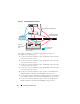
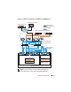
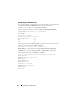
Figure 5-2. Cabling iSCSI Switched Clusters
To configure your nodes in a switched configuration, see Figure 5-2,
and complete the following steps:
1
Connect one CAT 5e/6 cable from a port (iSCSI HBA or NIC) of node 1
to the port of network switch 1.
2
Connect one CAT 5e/6 cable from a port (iSCSI HBA or NIC) of node 1
to the port of network switch 2.
3
Connect one CAT 5e/6 cable from a port (iSCSI HBA or NIC) of node 2
to the port of network switch 1.
4
Connect one CAT 5e/6 cable from a port (iSCSI HBA or NIC) of node 2
to the port of network switch 2.
5
Connect one CAT 5e/6 cable from a port of switch 1 to the
In-0
port of
RAID controller 0 in the PowerVault MD3000i storage enclosure.
6
Connect one CAT 5e/6 cable from the other port of switch 1 to the
In-0
port of RAID controller 1 in the PowerVault MD3000i storage enclosure.
7
Connect one CAT 5e/6 cable from a port of switch 2 to the
In-1
port of
RAID controller 0 in the PowerVault MD3000i storage enclosure.
LAN/WAN
Upto 16 Standalone Host Systems
IP SAN (Dual Gigabit
Ethernet Switches)
PowerVault MD3000i RAID Enclosure
(Dual-Controller)
Ethernet
Management
Port
CAT 5e/6 (Public NIC)
Fibre Optic Cables