
Owner's Manual


28 Setting Up a Fibre Channel Cluster
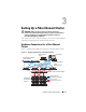
Table 3-1 lists the Fibre Channel hardware connections depicted in Figure 3-1
and summarises the cluster connections.
Table 3-1. Fibre Channel Hardware Interconnections
Cluster
Component
Connections
PowerEdge
system node
• One Category 5 enhanced (CAT 5e) or CAT 6 cable from
the public NIC to the LAN
• One CAT 5e or CAT 6 cable from the private Gigabit NIC
to the Gigabit Ethernet switch
• One CAT 5e or CAT 6 cable from a redundant private Gigabit NIC
to a redundant Gigabit Ethernet switch
• One fibre optic cable from HBA 0 to Fibre Channel switch 0
• One fibre optic cable from HBA 1 to Fibre Channel switch 1
Dell/EMC
Fibre
Channel
storage
system
• Two CAT 5e or CAT 6 cables connected to the LAN
• One to four fibre optic cable connections to each Fibre Channel
switch. For example, for a four-port configuration:
–One
fibre optic cable
from SPA port 0 to Fibre Channel switch 0
–One
fibre optic cable
from SPA port 1 to Fibre Channel switch 1
–One
fibre optic cable
from SPB port 0 to Fibre Channel switch 1
–One
fibre optic cable
from SPB port 1 to Fibre Channel switch 0
Dell/EMC Fibre
Channel switch
• One to four fibre optic cable connections to the Dell/EMC Fibre
Channel storage system
• One fibre optic cable connection to each PowerEdge system HBA
Gigabit
Ethernet
switch
• One CAT 5e or CAT 6 connection to the private Gigabit NIC on
each PowerEdge system
• One CAT 5e or CAT 6 connection to the remaining Gigabit
Ethernet switch