
Owner's Manual


iSiSCSI Cluster Setup for Dell PowerVault MD3000i and MD1000 23
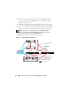
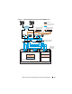
To configure your nodes in a switched configuration see Figure 4-2,
and complete the following steps:
1
Connect one CAT 5e/6 cable from a port (iSCSI HBA or NIC) of node 1
to the port of network switch 1.
2
Connect one CAT 5e/6 cable from a port (iSCSI HBA or NIC) of node 1
to the port of network switch 2.
3
Connect one CAT 5e/6 cable from a port (iSCSI HBA or NIC) of node 2
to the port of network switch 1.
4
Connect one CAT 5e/6 cable from a port (iSCSI HBA or NIC) of node 2
to the port of network switch 2.
5
Connect one CAT 5e/6 cable from a port of switch 1 to the In-0 port of
RAID controller 0 in the
Dell PowerVault
MD3000i storage enclosure.
6
Connect one CAT 5e/6 cable from the other port of switch 1 to the In-0
port of RAID controller 1 in the
Dell PowerVault
MD3000i
storage enclosure.
7
Connect one CAT 5e/6 cable from a port of switch 2 to the In-1 port of
RAID controller 0 in the
Dell PowerVault
MD3000i storage enclosure.
8
Connect one CAT 5e/6 cable from the other port of switch 2 to the In-1
port of RAID controller 1 in the
Dell PowerVault
MD3000i storage
enclosure.
9
Connect two SAS cables from the two MD3000i out ports to the two In
ports of the first
Dell PowerVault
MD1000 expansion enclosure (Optional).
10
Connect two SAS cables from the two MD1000 out ports to the In-0 ports
of the second
Dell PowerVault
MD1000 expansion enclosure (Optional).
NOTE: For information on configuring the Dell PowerVault MD1000 expansion
enclosure, see the Dell PowerVault MD3000 Storage System documentation
available on the Dell Support website at support.dell.com.
NOTE: See the Solutions Deliverable List (SDL) found at http://www.dell.com/
oracle and select the appropriate solution. After selecting the solution, verify that
the firmware version for your storage is at or above the required firmware version
found in the SDL.