
Owner's Manual


22 iSCSI Cluster Setup for Dell PowerVault MD3000i and MD1000
4
Connect one CAT 5e/6 cable from the other port (iSCSI HBA or NIC) of
node 2 to the In-1 port of RAID controller 1 in the
Dell PowerVault
MD3000i storage enclosure.
5
Connect two SAS cables from the two MD3000 out ports to the two In
ports of the first
Dell PowerVault
MD1000 expansion enclosure (Optional).
6
Connect two SAS cables from the two MD1000 out ports to the In-0 ports
of the second
Dell PowerVault
MD1000 expansion enclosure (Optional).
NOTE: For information on configuring the PowerVault MD1000 expansion
enclosure, see the Dell PowerVault MD3000 Storage System documentation
available on the Dell Support website at support.dell.com.
Switched iSCSI clusters can support up to eight nodes.
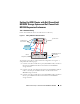
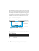
Figure 4-2. Cabling iSCSI Switched Clusters
To configure your nodes in a switched configuration see Figure 4-2, and
complete the following steps:
1
Connect one CAT 5e/6 cable from a port (iSCSI HBA or NIC) of node 1 to
the port of network switch 1.
2
Connect one CAT 5e/6 cable from a port (iSCSI HBA or NIC) of node 1 to
the port of network switch 2.
CAT 5e/6 (copper Gigabit (NIC)
Fiber optic cables
up to 16 standalone host
servers
IP SAN (dual Gigabit
Ethernet switches)
Ethernet management
port (2)
MD3000i RAID Enclosure
(dual controller)
corporate, public or
private network