
Owner's Manual

Fibre Channel Cluster Setup 13
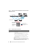
Before You Begin
Verify that the following tasks are completed for your cluster:
• All hardware components are installed in the rack.
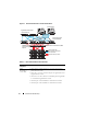
• All hardware interconnections are set up as shown in Figure 2-1 and
Figure 2-3, and
listed in Table 2-1.
• All logical unit numbers (LUNs), RAID groups, and storage groups are
created on the Dell/EMC Fibre Channel storage system.
• Storage groups are assigned to the nodes in the cluster.
CAUTION: Before you perform the procedures in the following sections,
ensure that the system hardware and cable connections are installed correctly.
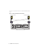
Dell/EMC
Fibre
Channel
storage
system
• Two CAT 5e or CAT 6 cables connected to the LAN
• One to four fiber optic cable connections to each Fibre Channel
switch. For example, for a four-port configuration:
–One
fiber optic cable
from SPA port 0 to Fibre Channel switch 0
–One
fiber optic cable
from SPA port 1 to Fibre Channel switch 1
–One
fiber optic cable
from SPB port 0 to Fibre Channel switch 1
–One
fiber optic cable
from SPB port 1 to Fibre Channel switch 0
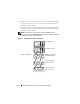
Dell/EMC Fibre
Channel switch
• One to four fiber optic cable connections to the Dell/EMC Fibre
Channel storage system
• One fiber optic cable connection to each PowerEdge system HBA
Gigabit
Ethernet
switch
• One CAT 5e or CAT 6 connection to the private Gigabit NIC on
each PowerEdge system
• One CAT 5e or CAT 6 connection to the remaining Gigabit
Ethernet switch
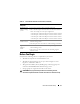
Table 2-1. Fibre Channel Hardware Interconnections (continued)
Cluster
Component
Connections