
Owner's Manual

6
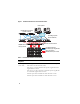
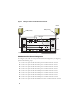
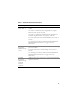
Figure 2. Cabling in a Direct-attached Fibre Channel Cluster
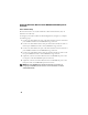
SAN-Attached Fibre Channel Configuration
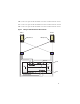
To configure your nodes in a four-port SAN-attached configuration (see Figure 3),
perform the following steps:
1
Connect one optical cable from SP-A port 0 to Fibre Channel switch 0.
2
Connect one optical cable from SP-A port 1 to Fibre Channel switch 1.
3
Connect one optical cable from SP-A port 2 to Fibre Channel switch 0.
4
Connect one optical cable from SP-A port 3 to Fibre Channel switch 1.
5
Connect one optical cable from SP-B port 0 to Fibre Channel switch 1.
6
Connect one optical cable from SP-B port 1 to Fibre Channel switch 0.
7
Connect one optical cable from SP-B port 2 to Fibre Channel switch 1.
8
Connect one optical cable from SP-B port 3 to Fibre Channel switch 0.
9
Connect one optical cable from HBA 0 on node 1 to Fibre Channel switch 0.
HBA ports (2)
Node 1
Node 2
HBA ports (2)
Dell|EMC CX3-80 Fibre Channel Storage
SP-B
SP-A
0
1
2
3
SP ports
3
2
1
0