
Owner's Manual

5
Cabling Your Fibre Channel Storage System
Depending on your needs, you can configure your Oracle fibre channel cluster
storage system in one of the following configurations:
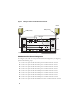
• Direct-attached fibre channel (see Figure 2)
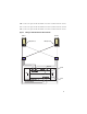
• Four-port SAN-attached fibre channel (Figure 3)
The following sections describe the cabling requirements for these configurations.
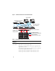
Direct-attached Fibre Channel Configuration
To configure your nodes in a Direct-attached fibre channel configuration
(see Figure 2), perform the following steps:
1
Connect one optical cable from HBA 0 on node 1 to port 0 of SP-A.
2
Connect one optical cable from HBA 1 on node 1 to port 0 of SP-B.
3
Connect one optical cable from HBA 0 on node 2 to port 1 of SP-A.
4
Connect one optical cable from HBA 1 on node 2 to port 1 of SP-B.
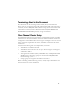
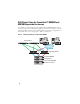
Dell|EMC
Fibre Channel
storage system
Two CAT 5e or CAT 6 cables connected to the LAN
One to four fiber optic cable connections to each Fibre Channel
switch. For example, for a four-port configuration:
•One
fiber optic cable
from SPA port 0 to Fibre Channel switch 0
•One
fiber optic cable
from SPA port 1 to Fibre Channel switch 1
•One
fiber optic cable
from SPB port 0 to Fibre Channel switch 1
•One
fiber optic cable
from SPB port 1 to Fibre Channel switch 0
Dell|EMC
Fibre Channel
switch
One to four fiber optic cable connections to the Dell|EMC Fibre
Channel storage system
One fiber optic cable connection to each PowerEdge system’s HBA
Gigabit
Ethernet
switch
One CAT 5e or CAT 6 connection to the private Gigabit NIC on
each PowerEdge system
One CAT 5e or CAT 6 connection to the remaining Gigabit
Ethernet switch
Table 1. Fibre Channel Hardware Interconnections (continued)
Cluster
Component
Connections