
Owner's Manual


15
3
Connect one CAT 5e/6 cable from a port (iSCSI HBA or NIC) of node 2 to
the In-1 port of RAID controller 0 in the MD3000i storage enclosure.
4
Connect one CAT 5e/6 cable from the other port (iSCSI HBA or NIC) of
node 2 to the In-1 port of RAID controller 1 in the MD3000i storage
enclosure.
5
(Optional). Connect two SAS cables from the two MD3000 out ports to the
two In ports of the first MD1000 expansion enclosure.
6
(Optional). Connect two SAS cables from the two MD1000 out ports to the
In-0 ports of the second MD1000 expansion enclosure.
NOTE: Refer to the MD3000i storage system documentation for information on
configuring the MD1000 expansion enclosures.
Switched iSCSI clusters can support up to eight nodes.
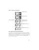
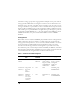
Figure 7. Cabling iSCSI Switched Clusters
1 up to 16 standalone host
servers
2 IP SAN (dual Gigabit Ethernet
switches
3 Ethernet management
port (2)
4 MD3000i RAID Enclosure
(dual controller)
5 corporate, public or private
network
1
2
3
4
5