Dell™ PowerEdge™ Systems Oracle Database 11g R1 on Red Hat® Enterprise Linux® 5 Advanced Server x86-64 or Oracle Enterprise Linux® 5 Advanced Server x86-64 Storage and Networking Guide Version 1.0 Overview of Oracle Database 11G Documentation The documentation set for the Oracle Database 11g R1 on Red Hat® Enterprise Linux® 5 Advanced Server x86-64 or Oracle Enterprise Linux® 5 Advanced Server x86-64 has been reorganized into a series of modules.
Notes, Cautions, and Warnings NOTE: A NOTE indicates important information that helps you make better use of your computer. ____________________ Information in this document is subject to change without notice. © 2009 Dell Inc. All rights reserved. Reproduction in any manner whatsoever without the written permission of Dell Inc. is strictly forbidden. Trademarks used in this text: Dell, the DELL logo, PowerEdge, and PowerVault are trademarks of Dell Inc.
Terminology Used in this Document This document uses the terms logical unit number (LUN) and virtual disk. These terms are synonymous and can be used interchangeably. The term LUN is commonly used in a Dell|EMC Fibre-Channel storage system environment and virtual disk is commonly used in a Dell PowerVault SAS (Dell MD3000i and Dell MD3000i with MD1000 expansion) storage environment. Fibre Channel Cluster Setup Your Dell Professional Services representative completed the setup of your Fibre Channel cluster.
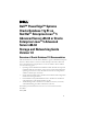
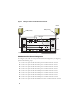
Figure 1. Hardware Connections for a Fibre Channel Cluster Client systems Gigabit Ethernet switches (private) network) PowerEdge systems (Oracle Database) Dell|EMC Fibre Channel storage systems Dell|EMC Fibre Channel switches (SAN) CAT 5e/6 (public NIC) CAT 5e/6 (copper Gigabit NIC) Fiber optic cables Additional fiber optic cables Table 1.
Table 1. Fibre Channel Hardware Interconnections (continued) Cluster Component Connections Dell|EMC Fibre Channel storage system Two CAT 5e or CAT 6 cables connected to the LAN Dell|EMC Fibre Channel switch One to four fiber optic cable connections to the Dell|EMC Fibre Channel storage system Gigabit Ethernet switch One CAT 5e or CAT 6 connection to the private Gigabit NIC on each PowerEdge system One to four fiber optic cable connections to each Fibre Channel switch.
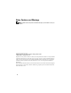
Figure 2. Cabling in a Direct-attached Fibre Channel Cluster Node 2 Node 1 HBA ports (2) HBA ports (2) SP ports SP-B 3 2 1 0 0 1 2 3 SP-A Dell|EMC CX3-80 Fibre Channel Storage SAN-Attached Fibre Channel Configuration To configure your nodes in a four-port SAN-attached configuration (see Figure 3), perform the following steps: 1 Connect one optical cable from SP-A port 0 to Fibre Channel switch 0. 2 Connect one optical cable from SP-A port 1 to Fibre Channel switch 1.
10 Connect one optical cable from HBA 1 on node 1 to Fibre Channel switch 1. 11 Connect one optical cable from HBA 0 on node 2 to Fibre Channel switch 0. 12 Connect one optical cable from HBA 1 on node 2 to Fibre Channel switch 1. Figure 3.
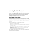
SAS Cluster Setup for PowerVault™ MD3000 and MD1000 Expansion Enclosures To configure your PowerEdge Systems and PowerVault MD3000 hardware and software to function in a Oracle Real Application Cluster environment, verify the following hardware connections and the hardware and software configurations as described in this section using Figure 4, Table 2, and Figure 5. Figure 4.
Table 2.
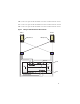
Setting Up SAS Cluster With PowerVault MD3000 and MD1000 Expansion Enclosures Task 1: Hardware Setup Because SAS clusters can only be installed in a direct-attached cluster, they are limited to two nodes only. To configure your nodes in a direct-attached configuration (see Figure 5), complete the following steps: 1 Connect one SAS cable from a port of the SAS controller of node 1 to the In-0 port of RAID controller 0 in the MD3000 storage enclosure.
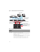
Figure 5. Cabling Direct-attached SAS Cluster Dual-HBA Host Server Dual-HBA Host Server RAID Controller Module 0 RAID Controller Module 1 MD3000 RAID Enclosure MD1000 Expansion Enclosure MD1000 Expansion Enclosure Task 2: Installing Host-based Software Needed for Storage To install the necessary host-based storage software for the PowerVault MD3000 storage system, use the Dell PowerVault Resource CD software that came with your MD3000 storage system.
Task 3: Verifying and Upgrading the Firmware • Discover the host server’s direct-attached storage using the Modular Disk Storage Manager software that is installed on the host server. • Verify that the firmware for the following storage components is at the minimum required version. Refer to the Solutions Deliverable List (SDL) for the firmware version requirements.
NOTE: If you are using a MD3000i with Oracle Enterprise Linux 5, use the following instructions: 1. Run the following script to install the multipath drive; do not install the multipath from the MD3000i MDSM CD: dell-oracle-deployment/scripts/standard/510rpms_scsi_linuxrdac.sh 2. When prompted to install the multipath during the MDSM installation, select "No" and continue installation. Table 3.
Setting Up iSCSI Cluster for PowerVault MD3000i and MD1000 Expansion Enclosures Task 1: Hardware Setup Direct-attached iSCSI clusters are limited to two nodes only. Figure 6.
3 Connect one CAT 5e/6 cable from a port (iSCSI HBA or NIC) of node 2 to the In-1 port of RAID controller 0 in the MD3000i storage enclosure. 4 Connect one CAT 5e/6 cable from the other port (iSCSI HBA or NIC) of node 2 to the In-1 port of RAID controller 1 in the MD3000i storage enclosure. 5 (Optional). Connect two SAS cables from the two MD3000 out ports to the two In ports of the first MD1000 expansion enclosure. 6 (Optional).
To configure your nodes in a switched configuration see Figure 7, and complete the following steps: 1 Connect one CAT 5e/6 cable from a port (iSCSI HBA or NIC) of node 1 to the port of network switch 1. 2 Connect one CAT 5e/6 cable from a port (iSCSI HBA or NIC) of node 1 to the port of network switch 2. 3 Connect one CAT 5e/6 cable from a port (iSCSI HBA or NIC) of node 2 to the port of network switch 1. 4 Connect one CAT 5e/6 cable from a port (iSCSI HBA or NIC) of node 2 to the port of network switch 2.
Task 2: Installing Host-based Software Needed for Storage To install the necessary host-based storage software for the PowerVault MD3000i storage system, use the Dell PowerVault Resource CD software that came with your MD3000i storage system. Follow the procedures in your Dell documentation that is included with the PowerVault MD3000i storage system to install the "Modular Disk Storage Manager Software" on the Master node and the Multi-Path (MPIO) software on the remaining nodes.
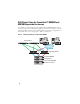
Cabling EqualLogic iSCSI Storage System Host servers can be attached to the Dell EqualLogic PS5000XV iSCSI array through an IP storage area network (SAN) industry-standard Gigabit Ethernet switch. "Recommended Network Configuration" on page 18 shows the recommended network configuration for a dual control module PS5000XV array. This configuration includes two Dell PowerConnect 6200 series Gigabit Ethernet switches, to provide highest network availability and maximum network bandwidth.
Figure 9. Sample Oracle RAC Configuration with three PS5000XV arrarys As illustrated in Figure 9, the group named oracle-group includes three PS5000XV members: oracle-member01, oracle-member02, and oraclemember03. When a member is initialized, it can be configured with RAID 10, RAID 5, or RAID 50. For more information on how to initialize an EqualLogic array, consult the Dell EqualLogic User's Guide.
A PS Series storage group can be segregated into multiple tiers or pools. Tiered storage provides administrators with greater control over how disk resources are allocated. At any one time, a member can be assigned to only one pool. It is easy to assign a member to a pool and also to move a member between pools with no impact to data availability. Pools can be organized according to different criteria, such as disk types or speeds, RAID levels, application types.
Table 4 shows a sample volume configuration. Create volumes in PS5000XV array and create access list to allow all host iSCSI network interfaces to access the volumes. For example, the following volumes are created: mdi-ocr-css-spfile mdi-data1 mdi-data2 mdi-fra1 Configuring iSCSI Networks Dell recommend configuring the host network interfaces for iSCSI traffic to use Flow Control and Jumbo Frame for optimal performance. Use the ethtool utility to configure Flow Control.
BOOTPROTO=none IPADDR=10.16.7.125 NETMASK=255.255.255.0 USERCTL=no MTU="9000" Verify the Jumbo Frame setting using the ifconfig command as follows: $ ifconfig eth2 eth2 Link encap:Ethernet HWaddr 00:15:17:80:43:50 inet addr:10.16.7.125 Bcast:10.16.7.255 Mask:255.255.255.
4 Obtain hardware address of each network interface on the host that will be used for iSCSI traffic. grep -i hwaddr /etc/sysconfig/network-scripts/ ifcfg-ethn n is the network interface number 5 Create an interface for each network interface on the host that will be used for iSCSI traffic. iscsiadm -m iface -I iface_name --op=new iface_name is the name assigned to the interface iscsiadm -m iface -I iface_name --op=update -n iface.
8 Restart iSCSI service for the new configuration to take effect. service iscsi stop service iscsi start 9 Discover targets from all ifaces created in step 5. iscsiadm -m discovery -t st -p group_ip_address -interface=iface_name1 --interface=iface_name2 -interface=iface_name3 --interface=iface_name4 group_ip_address is the IP address of the EqualLogic storage group.
10 Verify all volumes have been discovered from all the ifaces on the host. iscsiadm -m discovery --print=1 For example, # iscsiadm -m discovery --print=1 SENDTARGETS: DiscoveryAddress: 10.16.7.100,3260 Target: iqn.2001-05.com.equallogic:0-8a0906-90ee59d02e26f999767b4942e-mdi-ocr-css-spfile Portal: 10.16.7.100:3260,1 Iface Name: eth0-iface Iface Name: eth1-iface Target: iqn.2001-05.com.equallogic:0-8a0906-93ee59d02674f999767d4942e-mdi-data1 Portal: 10.16.7.
The following example logs into three volumes from each of the two ifaces (eth0-iface and eth1-iface) on a host. # iscsiadm -m node -p 10.16.7.100 --interface eth0-iface --login Logging in to [iface: eth0-iface, target: iqn.200105.com.equallogic:0-8a0906-90ee59d02-e26f999767b4942e-mdi-ocrcss-spfile, portal: 10.16.7.100,3260] Logging in to [iface: eth0-iface, target: iqn.200105.com.equallogic:0-8a0906-95ce59d02-2e0f999767f4942e-mdi-data2, portal: 10.16.7.
Logging in to [iface: eth1-iface, target: iqn.200105.com.equallogic:0-8a0906-97be59d02-d7ef99976814942e-mdi-fra1, portal: 10.16.7.100,3260] Login to [iface: eth1-iface, target: iqn.200105.com.equallogic:0-8a0906-90ee59d02-e26f999767b4942e-mdi-ocrcss-spfile, portal: 10.16.7.100,3260]: successful Login to [iface: eth1-iface, target: iqn.200105.com.equallogic:0-8a0906-95ce59d02-2e0f999767f4942e-mdi-data2, portal: 10.16.7.100,3260]: successful Login to [iface: eth1-iface, target: iqn.200105.com.
3 Add the following section in /etc/multipath.conf. The WWID is obtained from the step 1 above. Ensure the alias names are consistent on all hosts in the cluster. multipaths { multipath { wwid WWID_of_volume1 alias alias_of_volume1 } multipath { wwid WWID_of_volume2 alias alias_of_volume2 } (Add a multipath subsection for each additional volume.) } The following sample section includes configurations of four volumes.
For example, fra1 (36090a028d059be972e9414689799efd7) dm-13 EQLOGIC,100E-00 [size=5.0G][features=1 queue_if_no_path][hwhandler=0] \_ round-robin 0 [prio=0][enabled] \_ 96:0:0:0 sds 65:32 [active][ready] \_ round-robin 0 [prio=0][enabled] \_ 92:0:0:0 sdab 65:176 [active][ready] ocr-css-spfile (36090a028d059ee902e94b46797996fe2) dm-11 EQLOGIC,100E-00 [size=2.
brw-rw---- 1 root disk 253, 0 Dec 15 11:22 /dev/mapper/osvg-root brw-rw---- 1 root disk 253, brw-rw---- 1 root disk 253, 7 Dec 15 11:22 /dev/mapper/osvg-swap 1 Dec 15 11:22 /dev/mapper/osvg-tmp brw-rw---- 1 root disk 253, 2 Dec 15 11:22 brw-rw---- 1 root disk 253, /dev/mapper/osvg-usr 5 Dec 15 11:22 /dev/mapper/osvg-var Repeat step 1-8 on all other hosts in the cluster.
Configuring the Public Network NOTE: Ensure that your public IP address is a valid, routable IP address. NOTE: The two bonded NIC ports for a private network should be on separate PCI buses. For example, a bonded pair can consist of one on-board NIC and one add-on NIC card. If you have not already configured the public network, do so by performing the following steps on each node: 1 Log in as root.
Configuring the Private Network Using Bonding Before you deploy the cluster, configure the private cluster network to allow the nodes to communicate with each other. This involves configuring network bonding and assigning a private IP address and hostname to each node in the cluster. To set up network bonding for Broadcom or Intel® NICs and configure the private network, perform the following steps on each node: 1 Log in as root. 2 Add the following line to the /etc/modprobe.
5 For each device that is a bond member, perform the following steps: a In the directory /etc/sysconfig/network-scripts/, edit lines in the ifcfg-ethn file as follows: DEVICE=ethn HWADDR= ONBOOT=yes TYPE=Ethernet USERCTL=no MASTER=bond0 SLAVE=yes BOOTPROTO=none b Type service network restart and ignore any warnings. 6 On each node, type ifconfig to verify that the private interface is functioning. The private IP address for the node should be assigned to the private interface bond0.
10 On each node, create or modify the /etc/hosts.equiv file by listing all of your public IP addresses or host names.
To verify that each node can detect each storage LUN or logical disk, perform the following steps: 1 For Dell|EMC Fibre Channel storage system, verify that the EMC® Navisphere® agent and the correct version of PowerPath® are installed on each node, and that each node is assigned to the correct storage group in your EMC Navisphere software. See the documentation that came with your Dell|EMC Fibre Channel storage system for instructions.
• The external storage logical volumes appear as SCSI devices, and each node is configured with the same number of LUNs/virtual disks. For example, if the node is configured with a SCSI drive or RAID container attached to a Fibre Channel storage device with three logical disks, sda identifies the node’s RAID container or internal drive, and emcpowera, emcpowerb, and emcpowerc identify the LUNs (or PowerPath pseudo devices).
This method is preferable to the LUN alignment offset method for LUNs that will have a snapshot, clone, or MirrorView image made of them. It is also preferred for SAN Copy sources and targets. Procedure: Using the fdisk Utility to Adjust a Disk Partition Use the following procedure to use the fdisk utility to adjust a disk partition. 1 At the command prompt, type the following: fdisk where is the name of the partition that you are adjusting.
5 Specify the new location on the disk partition for the beginning of data. For example: 128 6 At the command prompt, type the following fdisk utility argument: w The system displays the following message: The partition table has been altered! Calling ioctl() to re-read partition table. Syncing disks. 7 Repeat step 1 through step 6 for all Oracle data LUN’s. Configuring Shared Storage for Oracle Clusterware and the Database Using OCFS2 Before You Begin Using OCFS2 1 Log in as root.
b Generate the OCFS2 configuration file /etc/ocfs2/cluster.conf with a default cluster name of ocfs2 by typing the following in a terminal window: ocfs2console c From the menu, click Cluster→ Configure Nodes. If the cluster is offline, the console will start it. A message window appears displaying that information. Close the message window. The Node Configuration window appears. d To add nodes to the cluster, click Add. Type the node name (same as the host name) and the private IP.
c Start the O2CB service on all the nodes by typing: /etc/init.d/o2cb start 5 On the first node, for a Fibre Channel cluster, create one partition on each of the other two external storage devices with fdisk: a Create a primary partition for the entire device by typing: fdisk /dev/emcpowerX Type h for help within the fdisk utility.
7 On each node, perform the following steps: a Create mount points for each OCFS2 partition. To perform this procedure, create the target partition directories and set the ownerships by typing: mkdir -p /u01 /u02 /u03 chown -R oracle.
Configuring Shared Storage Using the Block Devices 1 On the first node, create six partitions on an external storage device with the fdisk utility: Type: fdisk /dev/emcpowerX and create six partitions of 300 MB each for the Oracle Cluster Repositories (OCR), Voting Disks, and the Oracle system parameter file.
b Add the voting disk names to the permissions.ini file. This file is located in the following directory: /dell-oracle-deployment/scripts/ [ocr] primary_ocr= mirror_ocr1= [vote] vote1= vote2= vote3= [asm] asm1= asm2= For example, if the voting disks are emcpowerb1, emcpowerb2, and emcpowerb3, then the permissions.
Configuring Shared Storage for the Database Using ASM To configure your cluster using ASM, perform the following steps on all nodes: 1 Log in as root. 2 On all the nodes, create one partition on each of the other two external storage devices with the fdisk utility: a Create a primary partition for the entire device by typing: fdisk /dev/emcpowerX NOTE: Type h for help within the fdisk utility.
2 Run the permissions.py script located under the /dell-oracledeployment/scripts/ folder once you have set your permissions.ini file: ./permissions.py 3 Run the following command to set the correct block device permissions: /etc/rc.local Configuring Shared Storage Using the ASM Library Driver 1 Log in as root.
6 Verify that the ASM disks are created and marked for ASM usage. In the terminal window, type the following and press : service oracleasm listdisks The disks that you created in step appear. For example: ASM1 ASM2 7 Ensure that the remaining nodes are able to access the ASM disks that you created in step .
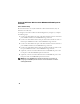
Oracle Support For training information on your Oracle software and application Clusterware, see the Oracle website at www.oracle.com or see your Oracle documentation for information about contacting Oracle. Technical support, downloads, and other technical information are available at the Oracle MetaLink website at www.metalink.oracle.com. For information on installing and configuring Oracle, continue to the Oracle Database Setup and Installation Guide.
Dell™ PowerEdge™ 系统 Red Hat® Enterprise Linux® 5 Advanced Server x86-64 或 Oracle Enterprise Linux® 5 Advanced Server x86-64 上的 Oracle Database 11g R1 存储设备和网络指南 1.
注、小心和警告 注:“注”表示可以帮助您更好地使用计算机的重要信息。 ____________________ 本说明文件中的信息如有更改,恕不另行通知。 © 2009 Dell Inc. 版权所有,翻印必究。 未经 Dell Inc. 书面许可,严禁以任何形式进行复制。 本文中使用的商标:Dell、 DELL 徽标、 PowerEdge 和 PowerVault 是 Dell Inc. 的商标; EMC、 PowerPath 和 Navisphere 是 EMC Corporation 的注册商标; Intel 是 Intel Corporation 的注册 商标; Red Hat 和 Red Hat Enterprise Linux 是 Red Hat, Inc 的注册商标。 本说明文件中述及的其它商标和产品名称是指拥有相应商标和产品名称的公司或其制造的产品。 Dell Inc.
本说明文件中使用的术语 本说明文件中使用了术语逻辑单元号码 (LUN) 和虚拟磁盘。这两个术语是同义 词并可互换使用。术语 LUN 通常在 Dell|EMC 光纤信道存储系统环境中使用, 而虚拟磁盘通常在 Dell PowerVault SAS (带有 MD1000 扩充的 Dell MD3000i 和 Dell MD3000i)存储环境中使用。 光纤信道群集设置 Dell 专业服务代表已为您完成了光纤信道群集的设置。请按照本节中的说明验 证硬件连接、硬件及软件配置。图 1 和图 3 所示为群集所需连接的概览,而表 1 概述了群集连接。 验证是否已为群集完成以下任务: • 所有硬件均已安装在机架中。 • 所有硬件互连均已如图 1、图 3 和表 1 所示进行设置。 • 所有逻辑单元号码 (LUN)、独立磁盘冗余阵列 (RAID) 组和存储组均在 Dell|EMC 光纤信道存储系统上创建。 • 存储组已分配给群集中的节点。 继续进行以下各节之前,目测检查所有硬件和互连情况,确保安装正确。 51
图 1. 光纤信道群集的硬件连接 客户机系统 吉位以太网交换机 (专用网络) PowerEdge 系统 (Oracle 数据库) Dell|EMC 光纤信道存 储系统 表 1.
表 1.
图 2.
10 使用一根光缆从节点 1 上的 HBA 1 连接至光纤信道交换机 1。 11 使用一根光缆从节点 2 上的 HBA 0 连接至光纤信道交换机 0。 12 使用一根光缆从节点 2 上的 HBA 1 连接至光纤信道交换机 1。 图 3.
PowerVault™ MD3000 和 MD1000 扩充硬盘柜的 SAS 群集设置 要配置 PowerEdge 系统以及 PowerVault MD3000 硬件和软件以使其在 Oracle Real Application Cluster 环境中正常工作,请按照本节中的说明使用图 4、 表 2 和图 5 验证以下硬件连接以及硬件和软件配置。 图 4.
表 2.
4 使用一根 SAS 电缆从节点 2 的 SAS 控制器另一个端口连接至 MD3000 存 储设备硬盘柜中 RAID 控制器 1 的 In-1 端口。 5 (可选)。使用两根 SAS 电缆从两个 MD3000 输出端口连接至第一个 MD1000 扩充硬盘柜的两个 In (输入)端口。 6 (可选)。使用两根 SAS 电缆从两个 MD1000 输出端口连接至第二个 MD1000 扩充硬盘柜的两个 In-0 端口。 注:请参阅 MD3000 存储系统的说明文件以了解有关配置 MD1000 扩充硬盘柜的 信息。说明文件位于 www.support.dell.com。 图 5.
任务 2:安装存储设备所需的基于主机的软件 要安装用于 PowerVault MD3000 存储系统的基于主机的必需存储软件,请使用 随 MD3000 存储系统附带的 Dell PowerVault Resource CD 软件。请遵循随 PowerVault MD3000 存储系统附带的 Dell 说明文件中的过程进行操作,在主节 点上安装 “Modular Disk Storage Manager 软件”并在其余节点上安装多路径 (MPIO) 软件。 任务 3:验证和升级固件 • 使用安装在主机服务器上的 Modular Disk Storage Manager 软件搜索主机 服务器的直接连接存储设备。 • 验证以下存储组件的固件是否满足最低所需版本。请参阅 Solutions Deliverable List (可提供的解决方案列表, SDL)以了解固件版本要求。 • RAID 控制器固件 • MD3000 存储系统固件 • MD1000 扩充硬盘柜固件 安装 SAS 5/E 适配器驱动程序 遵循随 MD3000 和 SAS HBA 附带的说明文件进行操作,在群集的两个节点上 安装
PowerVault MD3000i 和 MD1000 扩充硬盘柜的 iSCSI 群集设置 本节提供有关配置 PowerEdge 系统以及 PowerVault MD3000i 硬件和软件,使其 在 Oracle Real Application Cluster 环境中正常工作的信息和过程。 使用 Dell PowerVault MD3000i 支持值表中包含的 “支持的配置”图验证硬件连 接以及硬件和软件配置。以下网站提供本说明文件:www.support.dell.com。 注:如果使用带有 Oracle Enterprise Linux 5 的 MD3000i,则使用以下说明: 1. 运行以下脚本以安装多路径驱动器;请勿从 MD3000i MDSM CD 安装多路径: dell-oracle-deployment/scripts/standard/510rpms_scsi_linuxrdac.sh 2. 当 MDSM 安装过程中提示安装多路径时,请选择 No(否)并继续安装。 表 3.
设置 PowerVault MD3000i 和 MD1000 扩充硬盘柜的 iSCSI 群集 任务 1:硬件设置 直接连接的 iSCSI 群集仅限于两个节点。 图 6.
6 (可选)。使用两根 SAS 电缆从两个 MD1000 输出端口连接至第二个 MD1000 扩充硬盘柜的两个 In-0 端口。 注:请参阅 MD3000i 存储系统的说明文件以了解有关配置 MD1000 扩充硬盘柜的 信息。 交换式 iSCSI 群集可以支持最多八个节点。 图 7.
3 使用一根 CAT 5e/6 电缆从节点 2 的端口 (iSCSI HBA 或 NIC)连接至网 络交换机 1 的端口。 4 使用一根 CAT 5e/6 电缆从节点 2 的端口 (iSCSI HBA 或 NIC)连接至网 络交换机 2 的端口。 5 使用一根 CAT 5e/6 电缆从交换机 1 的一个端口连接至 MD3000i 存储设备 硬盘柜中 RAID 控制器 0 的 In-0 端口。 6 使用一根 CAT 5e/6 电缆从交换机 1 的另一个端口连接至 MD3000i 存储设 备硬盘柜中 RAID 控制器 1 的 In-0 端口。 7 使用一根 CAT 5e/6 电缆从交换机 2 的一个端口连接至 MD3000i 存储设备 硬盘柜中 RAID 控制器 0 的 In-1 端口。 8 使用一根 CAT 5e/6 电缆从交换机 2 的另一个端口连接至 MD3000i 存储设 备硬盘柜中 RAID 控制器 1 的 In-1 端口。 9 (可选)。使用两根 SAS 电缆从两个 MD3000i 输出端口连接至第一个 MD1000 扩充硬盘柜的两个 In (输入)端口。 10 (可选)。使用两根 SAS 电缆从两个
安装后任务 安装驱动程序和软件后,请执行 MD3000i Installation Guide (MD3000i 安装 指南)中列出的安装后任务,创建如第 60 页上的表 3 中所示的环境。 用于 EqualLogic PS 系列存储系统的 iSCSI 群集设置 EqualLogic 术语 EqualLogic PS 系列存储阵列包括存储虚拟化技术。为了更好地了解这些阵列的 原理,熟悉一些用于描述这些阵列及其功能的术语将非常有用: • 成员:一个单独的 PS 系列阵列即是一个成员 • 组:一个或多个可集中管理的成员的集合;主机服务器通过一个单独的组 IP 地址访问数据 • 池:可由一个或多个成员的磁盘组成的 RAID • 卷:代表池容量子集的 LUN 或虚拟磁盘 EqualLogic iSCSI 存储系统布线 主机服务器可通过 IP 存储区域网络 (SAN) 行业标准千兆位以太网交换机连接 至 Dell EqualLogic PS5000XV iSCSI 阵列。 第 65 页上的 “推荐的网络配置” 显示了双控制模块 PS5000XV 阵列的建议网络配置。此配置包括两台 Dell Pow
图 8.
图 9.
创建卷 必须先将 PS5000XV 物理磁盘配置到可用组件 (即卷)中,才能存储数据。 卷代表存储池的一部分,具有特定容量、访问控制和其它属性。卷可以跨越多 个磁盘和组成员,在网络上显示为 iSCSI 目标。卷分配给池并可以在不同的池 间轻松移动,而且不会影响数据的可用性。此外,池内还会自动存放数据, 以及根据池内存储硬件资源的总工作负载自动平衡负载。 表 4.
配置 iSCSI 网络 Dell 建议将用于 iSCSI 通信的主机网络接口配置为使用流控制和巨型帧以获得 最佳性能。使用 ethtool 公用程序配置流控制。 使用以下命令检查接口上的流控制 (RX/TX 暂停): # ethtool -a < 接口 > 例如: # ethtool -a eth2 Pause parameters for eth2: Autonegotiate: on RX: on TX: on 此示例显示流控制已开启。如果流控制尚未开启,请使用以下命令开启: # ethtool -A < 接口 > rx on tx on 通过添加 MTU="" 参数,即可在 /etc/sysconfig/networkscripts/ifcfg-< 接口 > 脚本中配置巨型帧。 以下示例中, MTU 被设置为 9000。 # cat /etc/sysconfig/network-scripts/ifcfg-eth2 DEVICE=eth2 HWADDR=00:15:17:80:43:50 ONBOOT=yes TYPE=Ethernet BOOTPROTO=none IPADDR=10.
使用如下 ifconfig 命令验证巨型帧设置: $ ifconfig eth2 eth2 Link encap:Ethernet HWaddr 00:15:17:80:43:50 inet addr:10.16.7.125 Bcast:10.16.7.255 Mask:255.255.255.0 inet6 addr: fe80::215:17ff:fe80:4350/64 Scope:Link UP BROADCAST RUNNING MULTICAST MTU:9000 Metric:1 RX packets:3348411 errors:0 dropped:0 overruns:0 frame:0 TX packets:2703578 errors:0 dropped:0 overruns:0 carrier:0 collisions:0 txqueuelen:1000 RX bytes:10647052076(9.9 GiB)TX bytes:11209177325(10.
5 为要用于 iSCSI 通信的主机上的每个网络接口创建接口。 iscsiadm -m iface -I iface_name --op=new iface_name 是指定给接口的名称 iscsiadm -m iface -I iface_name --op=update -n iface.hwaddress -v hardware_address hardware_address 是步骤 4 中获取的接口硬件地址 例如,以下命令将为硬件地址为 00:18:8B:4E:E6:CC 的 eth0 接口创建名为 eth0-iface 的接口。 # iscsiadm -m iface -I eth0-iface --op=new New interface eth0-iface added # iscsiadm -m iface -I eth0-iface --op=update -n iface.
9 从步骤 5 创建的所有接口搜索目标。 iscsiadm -m discovery -t st -p group_ip_address -interface=iface_name1 --interface=iface_name2 -interface=iface_name3 --interface=iface_name4 group_ip_address 是 EqualLogic 存储组的 IP 地址。 iface_name1、 iface_name2、 iface_name3、 iface_name4 (…) 是将用于 iSCSI 通信的主机上的网络接口 (在步骤 5 中定义)。 例如,以下命令在组 IP 地址 10.16.7.100 上从具有两个接口(eth0-iface 和 eth1-iface)的主机中搜索到四个卷。 # iscsiadm -m discovery -t st -p 10.16.7.100 -interface=eth0-iface --interface=eth1-iface 10.16.7.100:3260,1 iqn.2001-05.com.
SENDTARGETS: DiscoveryAddress: 10.16.7.100,3260 Target: iqn.2001-05.com.equallogic:0-8a0906-90ee59d02e26f999767b4942e-mdi-ocr-css-spfile Portal: 10.16.7.100:3260,1 Iface Name: eth0-iface Iface Name: eth1-iface Target: iqn.2001-05.com.equallogic:0-8a0906-93ee59d02674f999767d4942e-mdi-data1 Portal: 10.16.7.100:3260,1 Iface Name: eth0-iface Iface Name: eth1-iface Target: iqn.2001-05.com.equallogic:0-8a0906-95ce59d022e0f999767f4942e-mdi-data2 Portal: 10.16.7.
# iscsiadm -m node -p 10.16.7.100 --interface eth0-iface --login Logging in to [iface: eth0-iface, target: iqn.200105.com.equallogic:0-8a0906-90ee59d02-e26f999767b4942e-mdi-ocrcss-spfile, portal: 10.16.7.100,3260] Logging in to [iface: eth0-iface, target: iqn.200105.com.equallogic:0-8a0906-95ce59d02-2e0f999767f4942e-mdi-data2, portal: 10.16.7.100,3260] Logging in to [iface: eth0-iface, target: iqn.200105.com.equallogic:0-8a0906-93ee59d02-674f999767d4942e-mdi-data1, portal: 10.16.7.
Login to [iface: eth1-iface, target: iqn.200105.com.equallogic:0-8a0906-90ee59d02-e26f999767b4942e-mdi-ocrcss-spfile, portal: 10.16.7.100,3260]: successful Login to [iface: eth1-iface, target: iqn.200105.com.equallogic:0-8a0906-95ce59d02-2e0f999767f4942e-mdi-data2, portal: 10.16.7.100,3260]: successful Login to [iface: eth1-iface, target: iqn.200105.com.equallogic:0-8a0906-93ee59d02-674f999767d4942e-mdi-data1, portal: 10.16.7.100,3260]: successful Login to [iface: eth1-iface, target: iqn.200105.com.
3 在 /etc/multipath.
例如: fra1 (36090a028d059be972e9414689799efd7) dm-13 EQLOGIC,100E-00 [size=5.0G][features=1 queue_if_no_path][hwhandler=0] \_ round-robin 0 [prio=0][enabled] \_ 96:0:0:0 sds 65:32 [active][ready] \_ round-robin 0 [prio=0][enabled] \_ 92:0:0:0 sdab 65:176 [active][ready] ocr-css-spfile (36090a028d059ee902e94b46797996fe2) dm-11 EQLOGIC,100E-00 [size=2.
brw-rw---- 1 root disk 253, 7 Dec 15 11:22 /dev/mapper/osvg-swap brw-rw---- 1 root disk 253, brw-rw---- 1 root disk 253, 1 Dec 15 11:22 /dev/mapper/osvg-tmp 2 Dec 15 11:22 /dev/mapper/osvg-usr brw-rw---- 1 root disk 253, 5 Dec 15 11:22 /dev/mapper/osvg-var 在群集中的所有其它主机上重复步骤 1 至 8。 配置 Oracle 11g RAC 的存储和网络 本节介绍有关设置光纤信道、 iSCSI 或直接连接的 SAS 群集 (运行基础数 据库)的信息和过程: • 配置公用和专用网络 • 使用 OCFS2 或 ASM 配置用于 Oracle 群集件和数据库的共享存储设备 Oracle 11g RAC 是一项复杂的数据库配置,要求按顺序执行以下一系列过程。 要想用最少的时间配置网络和存储设备,请按顺序执行以下过程。 配置公用和专用网络 本节将
配置公用网络 注:确保公用 IP 地址是有效且可路由的 IP 地址。 注:专用网络的两个绑定的 NIC 端口应位于独立的 PCI 总线上。例如,一个绑 定对可由一个板载 NIC 和一个添加式 NIC 卡组成。 如果您尚未配置公用网络,请在每个节点上执行以下步骤进行配置: 1 作为 root 登录。 2 编辑网络设备文件 /etc/sysconfig/network-scripts/ifcfg-eth#,其中 # 是网 络设备号。 配置该文件如下: DEVICE=eth0 ONBOOT=yes IPADDR=< 公用 IP 地址 > NETMASK=< 子网掩码 > BOOTPROTO=static HWADDR= SLAVE=no 3 编辑 /etc/sysconfig/network 文件,如果有必要,使用完全限定的公用节点 名称替换 localhost.localdomain。 例如,节点 1 对应的行应该如下所示: hostname=node1.domain.
利用绑定功能配置专用网络 在部署群集之前,应将专用群集网络配置为允许节点之间相互通信。此过程包 括配置网络绑定以及为群集中的每个节点分配专用 IP 地址和主机名。 要设置 Broadcom 或 Intel® NIC 的网络绑定并配置专用网络,请在每个节点上 执行以下步骤: 1 作为 root 登录。 2 在 /etc/modprobe.conf 文件中添加以下行: alias bond0 bonding 3 为了获得高可用性,请编辑 /etc/modprobe.conf 文件并设置链接监测 选项。 miimon 的默认值为 0,该值会禁用链接监测功能。开始时将该值更改为 100 毫秒,然后根据需要进行调整以改善性能,如以下示例中所示。 键入: options bonding miimon=100 mode=6 max_bonds=2 4 在 /etc/sysconfig/network-scripts/ 目录中,创建或编辑 ifcfg-bond0 配置 文件。 例如,使用样本网络参数时,该文件会显示如下: DEVICE=bond0 IPADDR=192.168.0.1 NETMASK=255.255.
5 对于属于绑定成员的每个设备,执行以下步骤: a 在目录 /etc/sysconfig/network-scripts/ 中,编辑 ifcfg-ethn 文件中的行, 如下所示: DEVICE=ethn HWADDR= ONBOOT=yes TYPE=Ethernet USERCTL=no MASTER=bond0 SLAVE=yes BOOTPROTO=none b 键入 service network restart 并忽略任何警告。 6 在每个节点上,键入 ifconfig 以验证专用接口是否正常工作。 节点的专用 IP 地址应该分配给专用接口 bond0。 7 每个节点上均已设置专用 IP 地址后,请从一个节点 ping 每个 IP 地址, 确保专用网络可以正常工作。 8 连接至每个节点,并通过键入以下命令验证专用网络和 ssh 是否正常 工作: ssh < 专用 IP> 9 在每个节点上,通过键入以下命令修改 /etc/hosts 文件中的行: 127.0.0.1 localhost.
10 在每个节点上,通过列出所有公用 IP 地址或主机名来创建或修改 /etc/hosts.
要验证是否每个节点都能检测到各存储 LUN 或逻辑磁盘,请执行以下步骤: 1 对于 Dell|EMC 光纤信道存储系统,验证每个节点上是否均已安装了 EMC® Navisphere® 代理程序和正确版本的 PowerPath®,以及是否已在 EMC Navisphere 软件中将每个节点分配给正确的存储组。有关说明, 请参阅随 Dell|EMC 光纤信道存储系统附带的说明文件。 注:为您安装群集的 Dell 专业服务代表已执行此步骤。如果您在节点中重 新安装软件,则必须执行此步骤。 2 通过目测检查来验证存储设备和节点是否已正确连接至光纤信道交换机 (请参阅图 1 和表 1)。 3 验证您是否已作为 root 登录。 4 在每个节点上,键入: more /proc/partitions 节点将检测和显示 LUN 或逻辑磁盘,以及在这些外部设备上创建的分区。 注:列出的设备可能有所不同,具体视存储系统的配置而定。 屏幕将显示一个列表,列出节点检测到的 LUN 或逻辑磁盘以及在这些外 部设备上创建的分区。列表中还将显示 PowerPath 虚拟设备,如 /dev/emcpowera、 /dev/emcpowerb
• 外部存储设备的逻辑卷显示为 SCSI 设备,并且每个节点配置相同数 目的 LUN/ 虚拟磁盘。 例如,如果对节点进行配置,使 SCSI 驱动器或 RAID 容器连接至具 有三个逻辑磁盘的光纤信道存储设备,则 sda 可以识别节点的 RAID 容器或内部驱动器,而 emcpowera、 emcpowerb 和 emcpowerc 可以识 别 LUN (或 PowerPath 虚拟设备)。 如果对节点进行配置,使 SCSI 驱动器或 RAID 容器连接至具有三个 虚拟磁盘的直接连接 SAS 或 iSCSI 存储设备, sda 可以识别节点的 RAID 容器或内部驱动器,而 sdb、 sdc 和 sdd 可以识别外部存储设备 逻辑卷。 6 如果外部存储设备未出现在 /proc/partitions 文件中,请重新引导该节点。 调整 Linux 系统的磁盘分区 在 Linux 中,在数据写入到 LUN/ 虚拟磁盘之前对齐分区表,否则将会重写分 区映射并破坏 LUN/ 虚拟磁盘上的所有数据。 示例: fdisk 公用程序参数 以下示例表示 fdisk 公用程序的参数。在本例中, LUN 映射到 /dev/e
过程:使用 fdisk 公用程序调整磁盘分区 可通过以下步骤使用 fdisk 公用程序调整磁盘分区。 1 在命令提示符下,键入以下命令: fdisk < 分区名称 > 其中 < 分区名称 > 是您要调整的分区的名称。例如,如果分区名称为 /dev/emcpowera,您将键入: fdisk /dev/emcpowera 系统会显示以下信息: The number of cylinders for this disk is set to 8782. (此磁盘的磁柱数量设置为 8782。) There is nothing wrong with that, but this is larger than 1024, (这并没有问题,但由于该值大于 1024,) and could in certain setups cause problems with: (因此可能会在特定设置中导致以下问题:) 1) software that runs at boot time (e.g.
6 在命令提示符下,键入以下 fdisk 公用程序变量: w 系统会显示以下信息: The partition table has been altered! (分区表已变更!) Calling ioctl() to re-read partition table. (调用 ioctl() 以重新读取分区表。) Syncing disks. (正在同步磁盘。) 7 对所有 Oracle 数据 LUN 重复步骤 1 到步骤 6。 使用 OCFS2 配置用于 Oracle 群集件和数据库的共享存储设备 使用 OCFS2 的准备工作 1 作为 root 登录。 2 通过键入以下命令浏览至包含从 Dell Deployment CD 所安装的脚本的 目录: cd /dell-oracle-deployment/scripts/standard 3 通过键入以下命令,安装所有 OCFS 软件包: ./340-rpms-ocfs.
c 从菜单中,单击 Cluster (群集) → Configure Nodes (配置节点)。 如果群集脱机,则控制台将启动该群集。此时会出现一个信息窗口显 示该信息。关闭该信息窗口。 此时会出现 Node Configuration (节点配置)窗口。 d 要将节点添加至群集,请单击 Add (添加)。键入节点名称 (与主机 名相同)和专用 IP。保留端口号的默认值。键入所有详细信息后, 单击 OK (确定)。 重复此步骤以将所有节点添加至群集。 e 添加所有节点后,单击 Apply (应用),然后单击 Node Configuration (节点配置)窗口中的 Close (关闭)。 注:如果出现错误信息:Unable to access cluster service (无法访问群集服务),请删除以下文件: /etc/ocfs2/cluster.
5 对于光纤信道群集,在第一个节点上,使用 fdisk 在其它两个外部存储设 备上各创建一个分区: a 通过键入以下命令,创建整个设备的主分区: fdisk /dev/emcpowerX 键入 h,在 fdisk 公用程序内获取帮助。 b 通过键入以下命令,验证新分区是否存在: cat /proc/partitions c 如果没有看到新分区,请键入: sfdisk -R /dev/< 设备名称 > 注:以下步骤使用示例值: • 安装点:/u01、 /u02 和 /u03 • 标签:u01、 u02 和 u03 • 光纤信道存储设备:emcpowera、 emcpowerb 和 emcpowerc 6 在任一节点上,使用命令行公用程序 mkfs.ocfs2 以 4 K 数据块大小、128 K 群集大小和 4 个节点插槽 (节点插槽数是指群集节点数)格式化外部存储 设备,具体如下所示: ocr.dbf 和投票磁盘 mkfs.
7 在每个节点上,执行以下步骤: a 为每个 OCFS2 分区创建安装点。要执行此过程,请键入以下命令创 建目标分区目录和设置所有权: mkdir -p /u01 /u02 /u03 chown -R oracle.
2 键入以下命令,验证这些新分区: more /proc/partitions 如果新分区没有出现在 /proc/partitions 文件中,请在所有节点上,键入以 下命令: sfdisk -R /dev/< 设备名称 > 3 在光纤信道群集中的所有节点上,执行以下步骤: a 将主 OCR 和镜像 OCR 的分区名称添加到 permissions.ini 文件中。该文件位于以下目录: /dell-oracle-deployment/scripts/ [ocr] primary_ocr= mirror_ocr1= [vote] vote1= vote2= vote3= [asm] asm1= asm2= 例如,如果 OCR 和 OCR 镜像分区为 /dev/emcpowera1 和 /dev/emcpowera2,则 permissions.ini 将修改为如下形式: [ocr] primary_ocr=/dev/emcpowera1 mirror_ocr1=/dev/emcpowera2 b 将投票磁盘的名称添加到 permissions.
[asm] asm1= asm2= 例如,如果投票磁盘为 emcpowerb1、 emcpowerb2 和 emcpowerb3,则 permissions.ini 将修改为如下形式: [vote] vote1=/dev/emcpowerb1 vote2=/dev/emcpowerb2 vote3=/dev/emcpowerb3 注:仅修改上面列出的五个变量:primary_ocr、 mirror_ocr、 vote1、 vote2 和 vote3。 4 设置好 permissions.ini 文件后,请运行位于 /dell-oracledeployment/scripts/ 文件夹中的 permissions.py 脚本: ./permissions.py 5 运行以下命令以设置正确的块设备权限: /etc/rc.
使用块设备配置共享存储设备 1 将 asm1 和 asm2 的磁盘组名称添加到 permissions.ini 文件中。 该文件位于以下目录: /dell-oracle-deployment/scripts/ [asm] asm1= asm2= 例如,如果 ASM1 和 ASM2 磁盘组为 /dev/emcpowerc1 和 /dev/emcpowerd1,则 permissions.ini 将修改为如下形式: [asm] asm1=/dev/emcpowerc1 asm2=/dev/emcpowerd1 要额外添加使用 /dev/emcpowere1 的 ASM 磁盘组 ASM3,请在会话中再添 加一个条目: asm3=/dev/emcpowere1 2 设置好 permissions.ini 文件后,请运行位于 /dell-oracledeployment/scripts/ 文件夹中的 permissions.py 脚本: ./permissions.py 3 运行以下命令以设置正确的块设备权限: /etc/rc.
Start Oracle ASM library driver on boot (引导时启动 Oracle ASM 库 驱动程序) (y/n) [n]: y Fix permissions of Oracle ASM disks on boot (引导时修复 Oracle ASM 磁盘的权限) (y/n) [y]: y 3 仅当 RAC 配置使用 EqualLogic iSCSI 存储和 Linux Device Mapper Multipath 驱动程序时,才执行此步骤。按如下方式设置 /etc/sysconfig/oracleasm 中的 ORACLEASM_SCANORDER 参数: ORACLEASM_SCANORDER="dm" 重新引导服务器以使更改生效。 4 在第一个节点上 (在终端窗口中),键入以下命令并按 键: service oracleasm createdisk ASM1 /dev/emcpowerb1 service oracleasm createdisk ASM2 /dev/emcpowerc1 5 对所有需要创建的附加 ASM 磁盘,重复步骤 。 6 验证是否已
获得帮助 Dell 支持 有关系统使用方面的详情,请参阅随系统组件附带的说明文件。 有关白皮书、 Dell 支持的配置和一般信息,请访问 Dell|Oracle Tested and Validated Configurations (经 Dell|Oracle 测试和验证的配置)网站 dell.com/oracle。 要获得硬件和操作系统软件的 Dell 技术支持并下载最新的系统更新,请访问 Dell 支持网站 support.dell.com。与 Dell 联系的有关信息包含在系统的 《故障 排除指南》中。 我们现在还提供 Dell 企业培训与认证服务,请访问 dell.com/training 了解 详情。此培训服务可能并非在所有地区提供。 Oracle 支持 有关 Oracle 软件和应用程序群集件的培训信息,请访问 Oracle 网站 www.oracle.com 或参阅 Oracle 说明文件,了解关于联系 Oracle 的信息。 Oracle MetaLink 网站 www.metalink.oracle.
Systèmes Dell™ PowerEdge™ Oracle Database 11g R1 sur Red Hat® Enterprise Linux® 5 Advanced Server x86-64 ou Oracle Enterprise Linux® 5 Advanced Server x86-64 Guide de stockage et de mise en réseau Version 1.0 Présentation de la documentation d'Oracle Database 11G La documentation d'Oracle Database 11g R1 sur Red Hat® Enterprise Linux® 5 Advanced Server x86-64 ou Oracle Enterprise Linux® 5 Advanced Server x86-64 a été réorganisée et répartie en plusieurs modules.
Remarques, précautions et avertissements REMARQUE : Une REMARQUE indique des informations importantes qui peuvent vous aider à mieux utiliser votre ordinateur. ____________________ Les informations contenues dans ce document sont sujettes à modification sans préavis. © 2009 Dell Inc. Tous droits réservés. La reproduction de ce document de quelque manière que ce soit sans l'autorisation écrite de Dell Inc. est strictement interdite.
Terminologie utilisée dans ce document Les termes LUN (numéro d'unité logique) et disque virtuel sont synonymes et interchangeables. Le terme LUN est généralement utilisé pour les environnements de systèmes de stockage Fibre-Channel Dell|EMC, tandis que le terme disque virtuel est plutôt réservé aux environnements de stockage Dell PowerVault SAS (Dell MD3000i et Dell MD3000i avec châssis d'extension MD1000).
Figure 1. Connexions matérielles pour un cluster Fibre Channel Systèmes clients Commutateurs Ethernet Gigabit Réseau privé Systèmes PowerEdge (base de données Oracle) Systèmes de stockage Fibre Channel Dell|EMC Commutateurs Fibre Channel Dell|EMC (SAN) CAT 5e/6 (carte réseau (NIC) publique) CAT5e/6 (carte réseau Gigabit cuivre) Câbles à fibres optiques Câbles à fibres optiques supplémentaire Tableau 1.
Tableau 1.
Configuration Fibre Channel à connexion directe Pour créer une configuration Fibre Channel à connexion directe pour les nœuds du cluster (voir la figure 2), procédez comme suit : 1 Installez un câble optique entre l'adaptateur HBA 0 du nœud 1 et le port 0 du processeur de stockage A. 2 Installez un câble optique entre l'adaptateur HBA 1 du nœud 1 et le port 0 du processeur de stockage B. 3 Installez un câble optique entre l'adaptateur HBA 0 du nœud 2 et le port 1 du processeur de stockage A.
Configuration Fibre Channel avec connexion à un SAN Pour créer une configuration à 4 ports avec connexion à un SAN (voir la figure 3), procédez comme suit : 1 Installez un câble optique entre le port 0 du processeur de stockage A et le commutateur Fibre Channel 0. 2 Installez un câble optique entre le port 1 du processeur de stockage A et le commutateur Fibre Channel 1. 3 Installez un câble optique entre le port 2 du processeur de stockage A et le commutateur Fibre Channel 0.
Figure 3.
Configuration d'un cluster SAS pour un système de stockage PowerVault™ MD3000 et des châssis d'extension MD1000 Pour configurer les logiciels et le matériel des systèmes PowerEdge et du PowerVault MD3000 pour un environnement Oracle RAC (Real Application Cluster), vous devez vérifier les connexions du matériel ainsi que la configuration matérielle et logicielle. Pour ce faire, reportez-vous aux informations de la présente section (figure 4, tableau 2 et figure 5). Figure 4.
Tableau 2. Interconnexions matérielles d'un cluster SAS Composant du cluster Connexions Pour chaque nœud Un câble CAT5e/6 reliant la carte réseau (NIC) publique du système au réseau local (LAN) PowerEdge Un câble CAT5e/6 reliant la carte (NIC) Gigabit privée au commutateur Ethernet Gigabit (réseau privé). Un câble CAT5e/6 reliant la carte (NIC) Gigabit privée au commutateur Ethernet Gigabit (réseau privé).
Configuration d'un cluster SAS comprenant un système PowerVault MD3000 et des châssis d'extension MD1000 Tâche 1: installation du matériel Les clusters SAS ne peuvent être installés que dans un environnement à connexion directe ; ils sont donc limités à deux nœuds.
Figure 5. Câblage d'un cluster SAS à connexion directe Serveur hôte équipé de deux adaptateurs HBA Serveur hôte équipé de deux adaptateurs HBA Module contrôleur RAID 0 Module contrôleur RAID 1 Châssis RAID MD3000 Châssis d'extension MD1000 Châssis d'extension MD1000 Tâche 2 : installation des logiciels hôtes requis pour le stockage Pour installer les logiciels hôtes requis pour le système de stockage PowerVault MD3000, utilisez le disque Dell PowerVault Resource fourni avec ce système.
Tâche 3 : vérification et mise à niveau du micrologiciel • À l'aide du logiciel Modular Disk Storage Manager installé sur le serveur hôte, lancez la détection des unités de stockage directement connectées au serveur. • Vérifiez que vous disposez de la version minimale requise du micrologiciel des composants de stockage répertoriés ci-après. Reportez-vous au document “Solutions Deliverable List” (Liste des éléments pris en charge) pour identifier les versions de micrologiciel requises.
Configuration d'un cluster iSCSI pour un système PowerVault MD3000i et des châssis d'extension MD1000 Cette section fournit des informations et des procédures pour la configuration matérielle et logicielle des systèmes PowerEdge et PowerVault MD3000i afin qu'ils fonctionnent dans un environnement Oracle RAC (Real Application Cluster).
Tableau 3. Interconnexions de matériels iSCSI Composant du cluster Connexions Chaque système de stockage Dell PowerVault MD3000i Deux câbles CAT 5e/6 connectés au réseau local (un à partir de chaque processeur de stockage) pour l'interface de gestion Deux câbles CAT 5e/6 par processeur de stockage pour l'interconnexion iSCSI Pour des informations supplémentaires sur le système MD3000i, consultez la documentation relative à la configuration de PowerVault MD3000i.
Figure 6.
5 (Facultatif) Connectez deux câbles SAS entre les deux ports de sortie du MD3000 et les deux ports d'entrée (“In”) du premier châssis d'extension MD1000. 6 (Facultatif) Connectez deux câbles SAS entre les deux ports de sortie du MD1000 et les ports d'entrée (“In-0”) du second châssis d'extension MD1000. REMARQUE : Pour plus d'informations concernant la configuration des châssis d'extension MD1000, reportez-vous à la documentation du système de stockage MD3000i.
Pour configurer une liaison commutée pour les nœuds du cluster (voir la figure 7), procédez comme suit : 1 Installez un câble CAT 5e/6 entre un port (iSCSI HBA ou NIC) situé sur le nœud 1 et le port du commutateur réseau 1. 2 Installez un câble CAT 5e/6 entre un port (iSCSI HBA ou NIC) situé sur le nœud 1 et le port du commutateur réseau 2. 3 Installez un câble CAT 5e/6 entre un port (iSCSI HBA ou NIC) situé sur le nœud 2 et le port du commutateur réseau 1.
Tâche 2 : installation des logiciels hôtes requis pour le stockage Pour installer les logiciels hôtes requis pour le système de stockage PowerVault MD3000i, utilisez le disque Dell PowerVault Resource fourni avec ce système. Suivez les procédures décrites dans la documentation Dell fournie avec le PowerVault MD3000i pour installer le logiciel “Modular Disk Storage Manager” sur le nœud principal, et le logiciel multiacheminement (MPIO) sur les nœuds restants.
• Pool : désigne une matrice RAID qui peut être constituée de disques appartenant à un ou plusieurs membres • Volume : désigne un disque LUN ou virtuel constituant un sous-ensemble de la capacité d'un pool Câblage du système de stockage iSCSI EqualLogic Des serveurs hôtes peuvent être rattachés à la matrice iSCSI EqualLogic PS5000XV Dell via un commutateur Ethernet Gigabit standard pour réseaux SAN IP.
Figure 8. Configuration réseau recommandée La figure 9 présente l'architecture d'un exemple de configuration Oracle RAC à trois matrices PS5000XV. Les câbles bleus représentent le réseau SAN iSCSI. Les câbles gris représentent le réseau d'interconnexion privé Oracle RAC. Les câbles noirs représentent le réseau public. Les matrices de stockage PS5000XV fournissent la capacité de stockage physique de la base de données Oracle RAC.
Figure 9. Exemple de configuration Oracle RAC à trois matrices PS5000XV Comme le montre la figure 9, le groupe nommé oracle-group est constitué de trois membres PS5000XV : oracle-member01, oracle-member02 et oraclemember03. Lorsqu'un membre est initialisé, il peut être configuré avec un pool de stockage RAID 10, RAID 5 ou RAID 50. Pour plus d'informations sur l'initialisation d'une matrice EqualLogic, consultez le Dell EqualLogic User's Guide (Guide d'utilisation de Dell EqualLogic).
Un groupe de stockage série PS peut être subdivisé en plusieurs niveaux ou pools. Cette disposition permet aux administrateurs de mieux gérer la répartition de l'espace disque. Un membre peut à tout moment être affecté à un seul pool. On peut facilement affecter un membre à un pool ou le déplacer d'un pool à un autre sans aucune incidence sur la disponibilité des données.
Tableau 4. Configuration de volumes Oracle RAC (suite) Volume Taille minimale RAID Nombre de partitions Volume(s) de la troisième zone Au moins 5 deux fois la taille du ou des volumes de la deuxième zone Une Utilisé pour Adressage du système d'exploitation Zone de récupération Flash Groupe de disques ASM FLASHBACKDG Le tableau 4 présente un exemple de configuration des volumes.
Par exemple, # ethtool -a eth2 Pause parameters for eth2: Autonegotiate: on RX: on TX: on Dans cet exemple, le paramètre Flow Control (Contrôle de flux) est déjà activé. Si le paramètre Flow Control (Contrôle de flux) n'est pas activé, utilisez la commande suivante : # ethtool -A rx on tx on Le paramètre Jumbo Frame (Trame Jumbo) est configuré dans les scripts /etc/sysconfig/network-scripts/ifcfg-, en ajoutant le paramètre MTU="".
Configuration de l'accès des hôtes aux volumes Cette section décrit la procédure de configuration de l'accès des hôtes aux volumes iSCSI à l'aide de l'outil iscsiadm, qui est l'utilitaire d'administration open-iSCSI. 1 Connectez-vous au serveur en tant qu'utilisateur root. Vérifiez que le logiciel de l'initiateur open-iSCSI a été installé sur les serveurs hôtes. rpm -qa|grep -i iscsi-initiator La sortie ci-dessous devrait s'afficher si le package RPM de l'initiateur openiSCSI a été installé.
Par exemple, les commandes ci-dessous créent une interface nommée eth0iface pour l'interface eth0 dont l'adresse matérielle est 00:18:8B:4E:E6:CC. # iscsiadm -m iface -I eth0-iface --op=new New interface eth0-iface added # iscsiadm -m iface -I eth0-iface --op=update -n iface.hwaddress -v 00:18:8B:4E:E6:CC eth0-iface updated 6 Vérifiez que les interfaces ont été créées et correctement associées. iscsiadm -m iface 7 Modifiez les informations CHAP dans le fichier /etc/iscsi/iscsid.conf présent sur l'hôte.
Par exemple, la commande ci-dessous détecte quatre volumes à l'adresse IP de groupe 10.16.7.100, à partir d'un hôte à deux interfaces nommées eth0iface et eth1-iface. # iscsiadm -m discovery -t st -p 10.16.7.100 -interface=eth0-iface --interface=eth1-iface 10.16.7.100:3260,1 iqn.2001-05.com.equallogic:08a0906-90ee59d02-e26f999767b4942e-mdi-ocr-css-spfile 10.16.7.100:3260,1 iqn.2001-05.com.equallogic:08a0906-90ee59d02-e26f999767b4942e-mdi-ocr-css-spfile 10.16.7.100:3260,1 iqn.2001-05.com.
Target: iqn.2001-05.com.equallogic:0-8a0906-93ee59d02674f999767d4942e-mdi-data1 Portal: 10.16.7.100:3260,1 Iface Name: eth0-iface Iface Name: eth1-iface Target: iqn.2001-05.com.equallogic:0-8a0906-95ce59d022e0f999767f4942e-mdi-data2 Portal: 10.16.7.100:3260,1 Iface Name: eth0-iface Iface Name: eth1-iface Target: iqn.2001-05.com.equallogic:0-8a0906-97be59d02d7ef99976814942e-mdi-fra1 Portal: 10.16.7.100:3260,1 Iface Name: eth0-iface Iface Name: eth1-iface iSNS: No targets found. STATIC: No targets found.
Logging in to [iface: eth0-iface, target: iqn.200105.com.equallogic:0-8a0906-97be59d02-d7ef99976814942e-mdi-fra1, portal: 10.16.7.100,3260] Login to [iface: eth0-iface, target: iqn.200105.com.equallogic:0-8a0906-90ee59d02-e26f999767b4942e-mdi-ocrcss-spfile, portal: 10.16.7.100,3260]: successful Login to [iface: eth0-iface, target: iqn.200105.com.equallogic:0-8a0906-95ce59d02-2e0f999767f4942e-mdi-data2, portal: 10.16.7.100,3260]: successful Login to [iface: eth0-iface, target: iqn.200105.com.
12 Affichez et vérifiez toutes les connexions et sessions actives. iscsiadm -m session -i 13 Vérifiez que les partitions sont visibles dans le système d'exploitation. cat /proc/partitions 14 Répétez les étapes 1-13 sur chaque hôte du cluster.
L'exemple de section ci-dessous inclut les configurations de quatre volumes. multipaths { multipath { wwid alias } multipath { wwid alias } multipath { wwid alias } multipath { wwid alias } } 36090a028d059ee902e94b46797996fe2 ocr-css-spfile 36090a028d059ee902e94b46797996fe2 data1 36090a028d059ce952e94f46797990f2e data2 36090a028d059be972e9414689799efd7 fra1 4 Redémarrez le démon du multiacheminement, puis vérifiez que les alias s'affichent dans la sortie “multipath -ll”.
\_ 97:0:0:0 sdc 8:32 [active][ready] \_ round-robin 0 [prio=0][enabled] \_ 98:0:0:0 sdd 8:48 [active][ready] data1 (36090a028d059ee932e94d46797994f67) dm-18 EQLOGIC,100E-00 [size=20G][features=1 queue_if_no_path][hwhandler=0] \_ round-robin 0 [prio=0][enabled] \_ 95:0:0:0 sdq 65:0 [active][ready] \_ round-robin 0 [prio=0][enabled] \_ 89:0:0:0 sdac 65:192 [active][ready] 5 Vérifiez que les périphériques /dev/mapper/* ont été créés.
Configuration du réseau et du stockage pour Oracle 11g RAC Cette section contient des informations sur la configuration d'un cluster Fibre Channel, iSCSI ou SAS à connexion directe exécutant une base de données initiale : • Configuration des réseaux publics et privés • Configuration du stockage partagé pour Oracle Clusterware et Oracle Database à l'aide d'OCFS2 ou d'ASM La configuration d'une base de données sous Oracle11g RAC est complexe et nécessite une série ordonnée de procédures.
Configuration du réseau public REMARQUE : Vérifiez que l'adresse IP publique est valide et routable. REMARQUE : Les deux ports de la carte réseau (NIC) avec lien réseau pour un réseau privé doivent être sur des bus PCI séparés. Par exemple, une paire avec lien peut être composée d'une carte d'interface réseau (NIC) intégrée et d'une carte réseau (NIC) supplémentaire.
Configuration du réseau privé à l'aide de liens (bonding) Avant de déployer le cluster, vous devez configurer le réseau privé de manière à permettre aux nœuds de communiquer entre eux. Pour ce faire, il est nécessaire de configurer des liens réseau et d'attribuer une adresse IP privée et un nom d'hôte à chaque nœud du cluster.
5 Pour chaque périphérique faisant partie du lien, procédez comme suit : a Dans le répertoire /etc/sysconfig/network-scripts/, éditez les lignes du fichier ifcfg-ethn comme suit : DEVICE=ethn HWADDR= ONBOOT=yes TYPE=Ethernet USERCTL=no MASTER=bond0 SLAVE=yes BOOTPROTO=none b Tapez service network restart et ne tenez pas compte des avertissements. 6 Sur chaque nœud, tapez ifconfig pour vérifier le bon fonctionnement de l'interface privée.
9 Sur chaque nœud, modifiez les lignes du fichier /etc/hosts comme suit : 127.0.0.1 localhost.
Vérification de la configuration du stockage Les sections suivantes indiquent comment créer et configurer les partitions de disques pour le stockage Fibre Channel, iSCSI ou SAS à connexion directe. Création des partitions de disques sur un système de stockage Lors de la configuration des clusters, créez des partitions sur votre système de stockage Fibre Channel, iSCSI ou SAS à connexion directe.
3 Vérifiez que vous êtes connecté en tant que root. 4 Sur chaque nœud, tapez : more /proc/partitions Le nœud détecte, puis affiche les unités LUN ou disques logiques, ainsi que les partitions créées sur ces périphériques externes. REMARQUE : Les périphériques répertoriés varient en fonction de la configuration du système de stockage. La liste des LUN ou disques logiques détectés par le nœud s'affiche, ainsi que les partitions créées sur ces périphériques externes.
Si le nœud est configuré avec un lecteur SCSI ou un conteneur RAID connecté à un périphérique de stockage iSCSI ou SAS à connexion directe avec trois disques virtuels, sda identifie le conteneur RAID ou le lecteur interne du nœud, tandis que sdb, sdc et sdd identifient les volumes logiques de stockage externe. 6 Si les périphériques de stockage externes ne s'affichent pas dans le fichier /proc/partitions, redémarrez le nœud.
Procédure : utilisation de fdisk pour le paramétrage d'une partition de disque Procédez comme suit pour paramétrer une partition de disque à l'aide de l'utilitaire fdisk. 1 À l'invite de commande, tapez les commandes suivantes : fdisk où est le nom de la partition à paramétrer.
6 À l'invite, entrez l'argument fdisk suivant : w Le système affiche le message suivant pour indiquer que le nombre de cylindres du disque risque de poser problème dans certaines configurations : The partition table has been altered! Calling ioctl() to re-read partition table. Syncing disks. 7 Recommencez la procédure décrite de l'étape 1 à l'étape 6 pour chaque LUN de données Oracle.
c Dans le menu, sélectionnez Cluster → Configure Nodes (Configurer les nœuds). Si le cluster est hors ligne, la console le démarre. Une fenêtre de message s'affiche pour vous en informer. Fermez cette fenêtre. La fenêtre Node Configuration (Configuration du nœud) s'affiche. d Pour ajouter des nœuds au cluster, cliquez sur Add (Ajouter). Entrez le nom du nœud (le même que celui de l'hôte), ainsi que son adresse IP privée. Conservez le numéro de port par défaut.
b Modifiez O2CB_HEARTBEAT_THRESHOLD (dans le fichier /etc/sysconfig/o2cb) en indiquant la valeur 81 sur tous les nœuds. c Démarrez le service O2CB sur tous les nœuds en tapant : /etc/init.d/o2cb start 5 Si vous utilisez un cluster Fibre Channel, à partir du premier nœud, créez une partition sur chacun des deux autres périphériques de stockage partagés externes.
Zone de récupération Flash mkfs.ocfs2 -b 4K -C /dev/emcpowerc1 128K -N 4 -L u03 REMARQUE : Pour plus d'informations sur la définition des paramètres de format des clusters, voir www.oss.oracle.com/projects/ocfs2/dist/documentation/ocfs2_faq.html. 7 Procédez comme suit pour chacun des nœuds : a Créez des points de montage pour chaque partition OCFS2. Pour ce faire, créez les répertoires de la partition cible et définissez les propriétaires en tapant : mkdir -p /u01 /u02 /u03 chown -R oracle.
Configuration du stockage partagé pour Oracle Clusterware et Oracle Database à l'aide d'ASM Configuration du stockage partagé pour Oracle Clusterware Cette section indique comment configurer le stockage partagé pour Oracle Clusterware.
Par exemple, si les partitions OCR et miroir OCR sont /dev/emcpowera1 et /dev/emcpowera2, alors le fichier permissions.ini sera modifié comme suit : [ocr] primary_ocr=/dev/emcpowera1 mirror_ocr1=/dev/emcpowera2 b Ajoutez les noms des disques de vote dans le fichier permissions.ini.
Configuration du stockage partagé de la base de données à l'aide d'ASM Pour configurer le cluster avec ASM, effectuez la procédure suivante sur tous les nœuds : 1 Ouvrez une session en tant que root. 2 Sur tous les nœuds, créez une partition sur chacun des deux autres périphériques de stockage externes, à l'aide de fdisk : a Créez une partition principale pour l'ensemble du périphérique en tapant : fdisk /dev/emcpowerX REMARQUE : Pour consulter l'aide de l'utilitaire fdisk, tapez h.
Pour ajouter un groupe de disques ASM supplémentaire, ASM3, en utilisant /dev/emcpowere1, ajoutez une autre entrée à la session : asm3=/dev/emcpowere1 2 Exécutez le script permissions.py qui se trouve dans le dossier /delloracle-deployment/scripts/, une fois le fichier permissions.ini configuré : ./permissions.py 3 Exécutez la commande suivante pour définir les permissions appropriées pour les périphériques de bloc : /etc/rc.
5 Répétez l'étape pour chaque disque ASM supplémentaire à créer. 6 Vérifiez que les disques ASM sont créés et marqués pour l'utilisation d'ASM. Dans la fenêtre de terminal, tapez la commande suivante, puis appuyez sur : service oracleasm listdisks Les disques créés à l'étape s'affichent. Par exemple, ASM1 ASM2 7 Vérifiez que les autres nœuds peuvent accéder aux disques ASM créés à l'étape .
Support Oracle Pour obtenir des informations sur les formations concernant le logiciel Oracle et les clusters, visitez le site Web www.oracle.com. Vous pouvez aussi contacter Oracle à l'aide des coordonnées fournies dans la documentation. Le site Web www.metalink.oracle.com contient des informations de support technique, des fichiers téléchargeables et des informations diverses.
Dell™ PowerEdge™-Systeme Oracle Database 11g R1 mit Red Hat® Enterprise Linux® 5 Advanced Server x86-64 oder Oracle Enterprise Linux® 5 Advanced Server x86-64 Speicher- und Netzwerkhandbuch Version 1.0 Übersicht über die Dokumentation zu Oracle Database 11G Die Dokumentationen für Oracle Database 11g R1 mit Red Hat® Enterprise Linux® 5 Advanced Server x86-64 oder Oracle Enterprise Linux® 5 Advanced Server x86-64 wurden in einer Reihe von Modulen neu strukturiert.
Anmerkungen, Vorsichtshinweise und Warnungen ANMERKUNG: Eine ANMERKUNG macht auf wichtige Informationen aufmerksam, mit denen Sie das System besser einsetzen können. ____________________ Irrtümer und technische Änderungen vorbehalten. © 2009 Dell Inc. Alle Rechte vorbehalten. Nachdrucke jeglicher Art ohne die vorherige schriftliche Genehmigung von Dell Inc. sind strengstens untersagt. Marken in diesem Text: Dell, das DELL Logo, PowerEdge und PowerVault sind Marken von Dell Inc.
In diesem Dokument verwendete Terminologie In diesem Dokument werden die Begriffe Logische Gerätenummer (LUN) und Virtueller Datenträger verwendet. Diese Begriffe sind synonym und untereinander ersetzbar. Der Begriff LUN wird üblicherweise im Zusammenhang mit Dell|EMC Fibre-Channel-Speichersystemumgebungen und der Begriff virtuelles Laufwerk bei Dell PowerVault SAS-Speicherumgebungen (Dell MD3000i und Dell MD3000i mit Erweiterung MD1000) verwendet.
Abbildung 1. Hardwareverbindungen für einen Fibre-Channel-Cluster Client-Systeme Gigabit-Ethernet-Switches (privates) Netzwerk) PowerEdge-Systeme (Oracle-Datenbank) Dell|EMC Fibre-Channel-Switches (SAN) Dell|EMC FibreChannelSpeichersysteme Tabelle 1.
Tabelle 1. Fibre-Channel-Hardwareverbindungen (fortgesetzt) Clusterkomponente Verbindungen Dell|EMC FibreChannelSpeichersystem Zwei CAT 5e- oder CAT 6-Kabel zum LAN Dell|EMC FibreChannel-Switch Ein bis vier Glasfaserverbindungen zum Dell|EMC Fibre-ChannelSpeichersystem Ein bis vier Glasfaserverbindungen zu jedem Fibre-ChannelSwitch.
3 Verbinden Sie HBA 0 von Knoten 2 durch ein Glasfaserkabel mit Port 1 vom SP-A. 4 Verbinden Sie HBA 1 von Knoten 2 durch ein Glasfaserkabel mit Port 1 vom SP-B. Abbildung 2.
4 Installieren Sie ein Glasfaserkabel zwischen SP-A-Port 3 und Fibre-ChannelSwitch 1. 5 Installieren Sie ein Glaserfaserkabel zwischen Port 0 von SP-B und Fibre-Channel-Switch 1. 6 Installieren Sie ein Glaserfaserkabel zwischen Port 1 von SP-B und Fibre-Channel-Switch 0. 7 Installieren Sie ein Glaserfaserkabel zwischen SP-B-Port 2 und Fibre-ChannelSwitch 1. 8 Installieren Sie ein Glaserfaserkabel zwischen SP-B-Port 3 und Fibre-ChannelSwitch 0.
Abbildung 3.
SAS-Cluster-Einrichtung für PowerVault™ MD3000 und MD1000-Erweiterungsgehäuse Um Hardware und Software für Ihre PowerEdge-Systeme und PowerVault MD3000-Arrays für den Betrieb in einer Oracle Real Application ClusterUmgebung zu konfigurieren, überprüfen Sie die nachstehenden Hardwareverbindungen und die Hardware- und Softwarekonfigurationen wie in diesem Abschnitt beschrieben. Orientieren Sie sich dabei an Abbildung 4, Tabelle 2 und Abbildung 5. Abbildung 4.
Tabelle 2.
Einrichten eines SAS-Clusters mit PowerVault MD3000 und MD1000Erweiterungsgehäusen Schritt 1: Hardware-Setup SAS-Cluster lassen sich nur in einem Direct-Attach-Cluster installieren und sind deshalb auf zwei Knoten beschränkt. So richten Sie eine direkt verbundene Konfiguration (siehe Abbildung 5) für die Knoten ein: 1 Verbinden Sie einen Port des SAS-Controllers von Knoten 1 durch ein SASKabel mit Port In-0 von RAID-Controller 0 im MD3000-Speichergehäuse.
Abbildung 5. Verkabelung bei einem Direct-Attach-SAS-Cluster Hostserver mit zwei HBAs Hostserver mit zwei HBAs RAID-Controllermodul 0 RAID-Controllermodul 1 MD3000 RAID-Gehäuse MD1000-Erweiterungsgehäuse MD1000-Erweiterungsgehäuse Aufgabe 2: Installation der hostbasierten Speichersoftware Um die erforderliche hostbasierte Software für das PowerVault MD3000Speichersystem zu installieren, verwenden Sie die Dell PowerVault Resource-CD, die mit dem MD3000-Speichersystem geliefert wurde.
Schritt 3: Überprüfung und Upgrade der Firmware • Führen Sie mit der auf dem Hostserver installierten Software Modular Disk Storage Manager eine Erkennung des direkt verbundenen Speichers durch. • Stellen Sie sicher, dass die Firmware-Mindestanforderungen der folgenden Speicherkomponenten erfüllt sind. Die Angaben für die FirmwareMindestversionen finden Sie in der Solutions Deliverable List (SDL).
iSCSI-Cluster-Einrichtung für PowerVault MD3000i und MD1000-Erweiterungsgehäuse Dieser Abschnitt enthält Informationen und Anleitungen zum Konfigurieren von PowerEdge-Systemen und PowerVault MD3000i-Hardware und -Software in einer Oracle Real Application-Clusterumgebung. Überprüfen Sie die Hardwareverbindungen sowie die Hardware- und Softwarekonfigurationen mit den Angaben unter „Supported Configuration“ in der Dell PowerVault MD3000i Support Matrix. Dieses Dokument kann auf der Website www.support.dell.
Tabelle 3. iSCSI-Hardwareverbindungen Clusterkomponente Verbindungen Jedes Dell PowerVault MD1000-Speichererweiterungsgehäuse (optional) Für die MD1000-Erweiterungsgehäuse werden weitere Kabelverbindungen benötigt Einrichten eines iSCSI-Clusters für PowerVault MD3000i und MD1000Erweiterungsgehäuse Schritt 1: Hardware-Setup Direkt verbundene iSCSI-Cluster sind auf zwei Knoten beschränkt. Abbildung 6.
Um eine Direct-Attach-Konfiguration für die Knoten einzurichten, beachten Sie die Hinweise unter Abbildung 6, und führen Sie die folgenden Schritte durch: 1 Installieren Sie ein CAT 5e/6-Kabel zwischen einem Port (iSCSI-HBA oder NIC) von Knoten 1 und dem Port In-0 von RAID-Controller 0 im MD3000iSpeichergehäuse. 2 Installieren Sie ein CAT 5e/6-Kabel zwischen dem anderen Port (iSCSI-HBA oder NIC) von Knoten 1 und dem Port In-0 von RAID-Controller 1 im MD3000i-Speichergehäuse.
Abbildung 7. iSCSI-Cluster über Switches verkabeln 1 2 3 4 5 1 bis zu 16 eigenständige Hostserver 2 IP-SAN (zwei GigabitEthernet-Switches) 3 Ethernet-Verwaltungsschnittstelle (2) 4 MD3000i RAID-Gehäuse (zwei Controller) 5 Firmen-, öffentliches oder privates Netzwerk Um die Knoten über Switches zu konfigurieren (siehe Abbildung 7), gehen Sie wie folgt vor: 1 Installieren Sie ein CAT 5e/6-Kabel zwischen einem Port (iSCSI-HBA oder NIC) von Knoten 1 und dem Port von Netzwerkswitch 1.
5 Installieren Sie ein CAT 5e/6-Kabel zwischen einem Port von Switch 1 und dem Port In-0 von RAID-Controller 0 am MD3000i-Speichergehäuse. 6 Installieren Sie ein CAT 5e/6-Kabel zwischen dem anderen Port von Switch 1 und dem Port In-0 von RAID-Controller 1 am MD3000i-Speichergehäuse. 7 Installieren Sie ein CAT 5e/6-Kabel zwischen einem Port von Switch 2 und dem Port In-1 von RAID-Controller 0 am MD3000i-Speichergehäuse.
Schritt 3: Überprüfung und Upgrade der Firmware • Führen Sie mit der auf dem Hostserver installierten Software Modular Disk Storage Manager eine Erkennung des direkt verbundenen Speichers durch. • Stellen Sie sicher, dass die Firmware-Mindestanforderungen der folgenden Speicherkomponenten erfüllt sind. Die Angaben für die FirmwareMindestversionen finden Sie in der Solutions Deliverable List (SDL).
Verkabeln eines EqualLogic iSCSI-Speichersystems Hostserver können mit dem Dell EqualLogic PS5000XV iSCSI-Array über einen Industriestandard-Gigabit-Ethernet-Switch für IP-Speichernetzwerke (SAN) verbunden werden. „Empfohlene Netzwerkkonfiguration“ auf Seite 166 zeigt die empfohlene Netzwerkkonfiguration für ein PS5000XV-Array mit zwei Steuermodulen.
Abbildung 9. Oracle-RAC-Beispielkonfiguration mit drei PS5000XV-Arrays Wie in Abbildung 9 dargestellt, enthält die Gruppe „oracle-group“ drei PS5000XV-Mitglieder: oracle-member01, oracle-member02 und oraclemember03. Wenn ein Mitglied initialisiert wurde, kann es mit RAID 10, RAID 5 oder RAID 50 konfiguriert werden. Weitere Informationen zur Initialisierung eines EqualLogic-Arrays finden Sie im Dell EqualLogic-Benutzerhandbuch.
Eine PS-Speichergruppe kann in mehrere Stufen oder Pools unterteilt werden. Speicherstufen ermöglichen Administratoren eine bessere Steuerung der Zuweisung von Festplattenressourcen. Ein Mitglied kann jeweils nur einem Pool zugewiesen sein. Die Zuweisung von Mitgliedern zu einem Pool ist unkompliziert, und auch das Verschieben eines Mitglieds von einem Pool zu einem anderen beeinträchtigt die Datenverfügbarkeit nicht.
Tabelle 4. Volume Datenträger für Oracle-RAC-Konfiguration (fortgesetzt) Mindestgröße RAID Anzahl der Partitionen Datenträger Mindestens im dritten doppelt so Bereich groß wie die Datenträger im zweiten Bereich 5 Einer Verwendet für Betriebssystemzuweisung Wiederherstell ASM-Festplattenungsbereich gruppe FLASHBACKDG Tabelle 4 zeigt eine Datenträger-Beispielkonfiguration.
In diesem Beispiel ist Flow Control bereits aktiviert (on). Wenn die Flusskontrolle nicht aktiviert ist, verwenden Sie zum Aktivieren von Flow Control den folgenden Befehl: # ethtool -A rx on tx on Jumbo Frame wird in den Skripten in /etc/sysconfig/networkscripts/ifcfg- konfiguriert, indem Sie den Parameter MTU="" hinzufügen. Im folgenden Beispiel ist MTU auf 9000 gesetzt.
Konfiguration des Hostzugriffs auf Datenträger In diesem Abschnitt werden die einzelnen Schritte zur Konfiguration des Hostzugriffs auf iSCSI-Datenträger mithilfe des iscsiadm-Tools beschrieben. Bei diesem Tool handelt es sich um das Open-iSCSI-Administrationsprogramm. 1 Melden Sie sich als Benutzer „root“ beim Server an. Vergewissern Sie sich, dass die open-iSCSI-Initiatorsoftware auf allen Hostservern installiert wurde.
Mit den folgenden Befehlen wird zum Beispiel die Schnittstelle „eth0-iface“ erstellt, deren Hardwareadresse 00:18:8B:4E:E6:CC lautet. # iscsiadm -m iface -I eth0-iface --op=new New interface eth0-iface added # iscsiadm -m iface -I eth0-iface --op=update -n iface.hwaddress -v 00:18:8B:4E:E6:CC eth0-iface updated 6 Vergewissern Sie sich, dass die Schnittstellen erstellt und korrekt zugewiesen wurden. iscsiadm -m iface 7 Ändern Sie die die CHAP-Informationen in „/etc/iscsi/iscsid.conf “ auf dem Host. node.
Schnittstellenname1, Schnittstellenname2, Schnittstellenname3, Schnittstellenname4 (…) sind die Netzwerkschnittstellen (in Schritt 5 definiert) auf dem Host, der für den iSCSI-Datenverkehr verwendet wird. Mit dem folgenden Befehl werden zum Beispiel vier Datenträger unter der Gruppen-ID-Adresse 10.16.7.100 erkannt, von einem Host mit zwei Schnittstellen, deren Namen eth0-iface und eth1-iface lauten. # iscsiadm -m discovery -t st -p 10.16.7.100 -interface=eth0-iface --interface=eth1-iface 10.16.7.
Portal: 10.16.7.100:3260,1 Iface Name: eth0-iface Iface Name: eth1-iface Target: iqn.2001-05.com.equallogic:0-8a0906-93ee59d02674f999767d4942e-mdi-data1 Portal: 10.16.7.100:3260,1 Iface Name: eth0-iface Iface Name: eth1-iface Target: iqn.2001-05.com.equallogic:0-8a0906-95ce59d022e0f999767f4942e-mdi-data2 Portal: 10.16.7.100:3260,1 Iface Name: eth0-iface Iface Name: eth1-iface Target: iqn.2001-05.com.equallogic:0-8a0906-97be59d02d7ef99976814942e-mdi-fra1 Portal: 10.16.7.
Logging in to [iface: eth0-iface, target: iqn.200105.com.equallogic:0-8a0906-93ee59d02-674f999767d4942e-mdi-data1, portal: 10.16.7.100,3260] Logging in to [iface: eth0-iface, target: iqn.200105.com.equallogic:0-8a0906-97be59d02-d7ef99976814942e-mdi-fra1, portal: 10.16.7.100,3260] Login to [iface: eth0-iface, target: iqn.200105.com.equallogic:0-8a0906-90ee59d02-e26f999767b4942e-mdi-ocrcss-spfile, portal: 10.16.7.100,3260]: successful Login to [iface: eth0-iface, target: iqn.200105.com.
Login to [iface: eth1-iface, target: iqn.200105.com.equallogic:0-8a0906-93ee59d02-674f999767d4942e-mdi-data1, portal: 10.16.7.100,3260]: successful Login to [iface: eth1-iface, target: iqn.200105.com.equallogic:0-8a0906-97be59d02-d7ef99976814942e-mdi-fra1, portal: 10.16.7.100,3260]: successful 12 Zeigen Sie alle aktiven Verbindungen und Sitzungen an und überprüfen Sie sie. iscsiadm -m session -i 13 Vergewissern Sie sich, dass die Partitionen im Betriebssystem sichtbar sind.
3 Fügen Sie den folgenden Abschnitt in „/etc/multipath.conf “ ein. Die WWID wird im oben stehenden Schritt 1 bezogen. Stellen Sie sicher, dass die Aliasnamen auf allen Hosts im Cluster konsistent sind. multipaths { multipath { wwid WWID_von_Datenträger1 alias Alias_von_Datenträger1 } multipath { wwid WWID_von_Datenträger2 alias Alias_von_Datenträger2 } (Fügen Sie einen multipath-Teilabschnitt für jeden weiteren Datenträger hinzu.
4 Starten Sie den Multipath-Daemon neu, und vergewissern Sie sich, dass die Aliasnamen in der „multipath -ll“-Ausgabe angezeigt werden. service multipathd restart multipath -ll Beispiel: fra1 (36090a028d059be972e9414689799efd7) dm-13 EQLOGIC,100E-00 [size=5.
brw-rw---- 1 root disk 253, 13 Dec 15 11:51 /dev/mapper/fra1 brw-rw---- 1 root disk 253, 11 Dec 15 11:51 /dev/mapper/ocr-cssspfile brw-rw---- 1 root disk 253, brw-rw---- 1 root disk 253, 6 Dec 15 11:22 /dev/mapper/osvg-crs 3 Dec 15 11:22 /dev/mapper/osvg-home brw-rw---- 1 root disk 253, brw-rw---- 1 root disk 253, 4 Dec 15 11:22 /dev/mapper/osvg-opt 0 Dec 15 11:22 /dev/mapper/osvg-root brw-rw---- 1 root disk 253, brw-rw---- 1 root disk 253, 7 Dec 15 11:22 /dev/mapper/osvg-swap 1 Dec 15 11:22 /dev/mappe
Konfigurieren Sie die Schnittstellen je nach Anzahl der verfügbaren NIC-Ports wie in Tabelle 5 dargestellt. Tabelle 5. NIC-Port-Zuordnungen NIC-Port Drei verfügbare Ports Vier Ports verfügbar 1 Öffentliche IP und virtuelle IP Öffentliche IP 2 Private IP (gebunden) Private IP (gebunden) 3 Private IP (gebunden) Private IP (gebunden) 4 NA Virtuelle IP Konfiguration des öffentlichen Netzwerks ANMERKUNG: Stellen Sie sicher, dass die öffentliche IP-Adresse gültig und routingfähig ist.
3 Öffnen Sie die Datei /etc/sysconfig/network, und ersetzen Sie gegebenenfalls localhost.localdomain durch den vollständigen Namen des öffentlichen Knotens. Die Zeile für Knoten 1 würde beispielsweise wie folgt lauten: hostname=knoten1.domain.com 4 Geben Sie Folgendes ein: service network restart 5 Geben Sie ifconfig ein, um zu überprüfen, ob die IP-Adressen richtig eingerichtet wurden.
3 Um die Verfügbarkeit zu erhöhen, öffnen Sie die Datei /etc/modprobe.conf und aktivieren Sie die Option für Verbindungsüberwachung (Link Monitoring). Der Standardwert für miimon ist 0, wodurch die Verbindungsüberwachung deaktiviert wird. Ändern Sie den Wert zunächst auf 100 Millisekunden, und passen Sie ihn danach entsprechend der benötigten Leistung an, wie im folgenden Beispiel gezeigt.
5 Führen Sie für jedes Gerät, das Bestandteil der Bündelung ist, folgende Schritte aus: a Bearbeiten Sie im Verzeichnis /etc/sysconfig/network-scripts/ die Zeilen der Datei ifcfg-ethn wie folgt: DEVICE=ethn HWADDR= ONBOOT=yes TYPE=Ethernet USERCTL=no MASTER=bond0 SLAVE=yes BOOTPROTO=none b Geben Sie service network restart ein, und übergehen Sie etwaige Warnmeldungen. 6 Führen Sie auf jedem Knoten den Befehl ifconfig aus, um sicherzustellen, dass das private Netzwerk funktioniert.
ANMERKUNG: Die Beispiele in diesem und dem folgenden Schritt gelten für eine Konfiguration mit zwei Knoten. Für jeden weiteren Knoten müssen zusätzliche Zeilen hinzugefügt werden. 10 Erstellen oder bearbeiten Sie auf jedem Knoten die Datei /etc/hosts.equiv, indem Sie alle öffentlichen IP-Adressen oder Hostnamen aufführen.
Tabelle 6.
5 Stellen Sie in der Datei /proc/partitions Folgendes sicher: • Alle PowerPath-Pseudogeräte erscheinen in der Datei mit ähnlichen Gerätepfaden auf allen Knoten. Zum Beispiel /dev/emcpowera, dev/emcpowerb und /dev/emcpowerc. • Beim MD3000/MD3000i werden alle virtuellen Datenträger in der Datei an allen Knoten mit ähnlichen Gerätenamen angezeigt.
BEISPIEL: Parameter des Dienstprogramms fdisk Das folgende Beispiel verdeutlicht die Parameter für das Dienstprogramm fdisk. Die LUN ist in diesem Beispiel zu /dev/emcpowera zugeordnet, und die LUNStreifenelementgröße beträgt 128 Blocks. ANMERKUNG: Auf dem Datenträger /dev/emcpowera wurde im Beispiel bereits eine primäre Partition /dev/emcpowera1 erstellt. Beim MD3000/MD3000i müsste dieser Vorgang auf /dev/sdb1 durchgeführt werden.
Das System zeigt die folgende Meldung an: The number of cylinders for this disk is set to 8782. There is nothing wrong with that, but this is larger than 1024, and could in certain setups cause problems with: 1) software that runs at boot time (e.g., old versions of LILO) 2) booting and partitioning software from other OSs (e.g.
Konfigurieren von gemeinsamem Speicher für Oracle Clusterware und die Oracle-Datenbank mit OCFS2 Bevor Sie OCFS2 verwenden, führen Sie folgende Schritte durch: 1 Melden Sie sich als root beim System an. 2 Wechseln Sie zu dem Verzeichnis mit den Skripts von der Dell DeploymentCD, indem Sie eingeben: cd /dell-oracle-deployment/scripts/standard 3 Installieren Sie alle OCFS-Pakete, indem Sie Folgendes eingeben: ./340-rpms-ocfs.py 4 Wiederholen Sie Schritt 1 und Schritt 2 auf allen verbleibenden Knoten.
d Um dem Cluster Knoten hinzuzufügen, klicken Sie auf Add (Hinzufügen). Geben Sie den Knotennamen (gleich dem Hostnamen) und die private IP-Adresse ein. Übernehmen Sie den Standardwert für die Portnummer. Nachdem alle Eingaben gemacht sind, klicken Sie auf OK. Wiederholen Sie diesen Schritt, um dem Cluster alle Knoten hinzuzufügen. e Wenn alle Knoten hinzugefügt sind, klicken Sie auf Apply (Übernehmen), und klicken Sie dann im Fenster Node Configuration (Knoten-Konfiguration) auf Close (Schließen).
c Starten Sie den O2CB-Dienst auf allen Knoten, indem Sie Folgendes eingeben: /etc/init.d/o2cb start 5 Erstellen Sie bei einem Fibre-Channel-Cluster auf dem ersten Knoten mit fdisk eine Partition auf jedem der zwei anderen externen Speichergeräte: a Erstellen Sie eine Primärpartition für das gesamte Gerät, indem Sie eingeben: fdisk /dev/emcpowerX Hilfe für das Dienstprogramm fdisk erhalten Sie, indem Sie h drücken.
Wiederherstellungsbereich mkfs.ocfs2 -b 4K -C /dev/emcpowerc1 128K -N 4 -L u03 ANMERKUNG: Weitere Informationen über das Einstellen der Formatparameter bei Clustern erhalten Sie unter www.oss.oracle.com/projects/ocfs2/dist/documentation/ocfs2_faq.html. 7 Führen Sie auf jedem Knoten die folgenden Schritte aus: a Erstellen Sie für jede OCFS2-Partition Bereitstellungspunkte.
Gemeinsamen Speicher für Oracle Clusterware und die Oracle-Datenbank mit ASM konfigurieren Konfiguration des gemeinsamen Speichers für Oracle Clusterware Dieser Abschnitt enthält Anweisungen für die Konfiguration von gemeinsamem Speicher für Oracle Clusterware.
[asm] asm1= asm2= Wenn Ihre OCR- und OCR-Spiegelpartitionen zum Beispiel /dev/emcpowerc1 und /dev/emcpowerd2 sind, wird die Datei permissions.ini folgendermaßen geändert: [ocr] primary_ocr=/dev/emcpowera1 mirror_ocr1=/dev/emcpowera2 b Fügen Sie die Voting-Datenträgernamen der Datei permissions.ini hinzu.
4 Führen Sie das Skript permissions.py, das sich im Ordner /dell-oracledeployment/scripts/ befindet, aus, nachdem Sie die Datei permissions.ini eingerichtet haben: ./permissions.py 5 Geben Sie den folgenden Befehl ein, um die korrekten Blockgerätberechtigungen festzulegen: /etc/rc.local Konfiguration des gemeinsamem Speichers für die Datenbank mit ASM Um den Cluster mit ASM zu konfigurieren, führen Sie auf allen Knoten folgende Schritte durch: 1 Melden Sie sich als root beim System an.
Konfiguration von gemeinsamem Speicher mit Blockgeräten 1 Fügen Sie die Datenträgergruppennamen für asm1 und asm2 zur Datei permissions.ini hinzu. Diese Datei befindet sich im folgenden Verzeichnis: /dell-oracle-deployment/scripts/ [asm] asm1= asm2= Wenn Ihre ASM1- und ASM2-Datenträgergruppen zum Beispiel /dev/emcpowerc1 und /dev/emcpowerd1 sind, wird die Datei permissions.
Konfigurieren von gemeinsamem Speicher mit dem ASM-Bibliothekstreiber 1 Melden Sie sich als root beim System an. 2 Öffnen Sie ein Terminalfenster und führen Sie auf allen Knoten die folgenden Schritte durch: a Geben Sie ein: service oracleasm configure.
7 Stellen Sie sicher, dass die übrigen Knoten auf die in Schritt erstellten ASMDatenträger zugreifen können. Öffnen Sie auf jedem der übrigen Knoten ein Terminalfenster, geben Sie folgenden Befehl ein, und drücken Sie die : service oracleasm scandisks Wie Sie Hilfe bekommen Dell Support Weitere Informationen zum Betrieb des Systems erhalten Sie in der zusammen mit den Systemkomponenten gelieferten Dokumentation.
Dell™ PowerEdge™ システム Red Hat® Enterprise Linux® 5 Advanced Server x86-64/Oracle Enterprise Linux® 5 Advanced Server x86-64 上で使用する Oracle Database 11g R1 ストレージ & ネットワークガイド バージョン 1.
メモ、注意、警告 メモ:コンピュータを使いやすくするための重要な情報を説明しています。 ____________________ 本書の内容は予告なく変更されることがあります。 © 2009 すべての著作権は Dell Inc. にあります。 Dell Inc. の書面による許可のない複製は、いかなる形態においても厳重に禁じられています。 本書に使用されている商標:Dell、DELL ロゴ、PowerEdge、および PowerVault は Dell Inc. の商標です。EMC、PowerPath、および Navisphere は EMC Corporation の登録商標です。 Intel は Intel Corporation の登録商標です。Red Hat および Red Hat Enterprise Linux は Red Hat, Inc. の登録商標です。 商標または製品の権利を主張する事業体を表すためにその他の商標および社名が使用されて いることがあります。Dell Inc.
本書で使用されている用語 本書では、「論理ユニット番号」(LUN)および「仮想ディスク」という語が 使われています。これらの用語は同義語であり、どちらを使用しても構いま せん。「LUN」は Dell|EMC ファイバーチャネルストレージシステムの環 境で、「仮想ディスク」は Dell PowerVault SAS(Dell MD3000i および Dell MD3000i + MD1000 拡張)ストレージの環境で、通常使われる用語 です。 ファイバーチャネルクラスタのセットアップ お使いのファイバーチャネルクラスタは、デルの公認技術者によってセット アップが完了しています。本項の説明に従って、ハードウェアの接続、およ びハードウェアとソフトウェアの構成を確認してください。図 1 と 図 3 には クラスタに必要とされる接続の概要図を示します。また、表 1 にはクラスタ 接続についてまとめます。 クラスタについて、以下の各タスクが完了していることを確認します。 • すべてのハードウェアがラックに取り付けてある。 • すべてのハードウェアの接続が 図 1、図 3、表 1 に示すとおりにセット アップされ
図 1. ファイバーチャネルクラスタ用のハードウェアの接続 クライアントシステム ギガビットイーサネ ットスイッチ (プライベートネットワーク) PowerEdge システム (Oracle データベース) Dell | EMC ファイバーチャネル スイッチ(SAN) Dell|EMC ファイ バーチャネルス トレージシス テム 表 1.
表 1.
直接接続ファイバーチャネル構成 ノードを直接接続ファイバーチャネル構成(図 2 を参照)にするには、以下 の手順を実行します。 1 1 本の光ケーブルをノード 1 の HBA 0 から SP-A のポート 0 に接続し ます。 2 1 本の光ケーブルをノード 1 の HBA 1 から SP-B のポート 0 に接続し ます。 3 1 本の光ケーブルをノード 2 の HBA 0 から SP-A のポート 1 に接続し ます。 4 1 本の光ケーブルをノード 2 の HBA 1 から SP-B のポート 1 に接続し ます。 図 2.
SAN 接続のファイバーチャネル構成 ノードを 4 ポートの SAN 接続(図 3 を参照)で構成するには、以下の手順 を実行します。 1 1 本の光ケーブルを SP-A ポート 0 からファイバーチャネルスイッチ 0 に接続します。 2 1 本の光ケーブルを SP-A ポート 1 からファイバーチャネルスイッチ 1 に接続します。 3 1 本の光ファイバーケーブルを SP-A ポート 2 からファイバーチャネル スイッチ 0 に接続します。 4 1 本の光ファイバーケーブルを SP-A ポート 3 からファイバーチャネル スイッチ 1 に接続します。 5 1 本の光ケーブルを SP-B ポート 0 からファイバーチャネルスイッチ 1 に接続します。 6 1 本の光ケーブルを SP-B ポート 1 からファイバーチャネルスイッチ 0 に接続します。 7 1 本の光ファイバーケーブルを SP-B ポート 2 からファイバーチャネル スイッチ 1 に接続します。 8 1 本の光ファイバーケーブルを SP-B ポート 3 からファイバーチャネル スイッチ 0 に接続します。 9 1 本の光ケーブルをノード 1 の
図 3.
PowerVault™ MD3000/MD1000 拡張エンクロー ジャ用の SAS クラスタのセットアップ PowerEdge システムと PowerVault MD3000 のハードウェアとソフトウェ アが Oracle Real Application Cluster の環境で機能するように設定するには、 図 4、表 2、および 図 5 を参照し、本項の説明に従って、次のハードウェア 接続、およびハードウェアとソフトウェアの構成を確認してください。 図 4.
表 2.
PowerVault MD3000/MD1000 拡張エンクロージャを使用した SAS クラ スタのセットアップ タスク 1: ハードウェアのセットアップ SAS クラスタは直接接続クラスタ内にのみ取り付け可能であるため、2 ノー ドまでに限定されます。 ノードを直接接続(図 5 を参照)で構成するには、以下の手順を実行します。 1 ノード 1 の SAS コントローラのポートと MD3000 ストレージエンク ロージャ内の RAID コントローラ 0 の In-0 ポートを 1 本の SAS ケーブ ルで接続します。 2 ノード 1 の SAS コントローラのもう一方のポートと MD3000 ストレー ジエンクロージャ内の RAID コントローラ 1 の In-0 ポートを 1 本の SAS ケーブルで接続します。 3 ノード 2 の SAS コントローラのポートと MD3000 ストレージエンク ロージャ内の RAID コントローラ 0 の In-1 ポートを 1 本の SAS ケーブ ルで接続します。 4 ノード 2 の SAS コントローラのもう一方のポートと MD3000 ストレー ジエンクロージ
図 5.
タスク 3: ファームウェアの確認とアップグレード • ホストサーバーにインストールされている Modular Disk Storage Manager ソフトウェアを使用してホストサーバーの直接接続ストレー ジを検出します。 • 次のストレージコンポーネント用のファームウェアが最低必要なバー ジョンであることを確認します。ファームウェアのバージョン要件につ いては、Solutions Deliverable List(SDL)(ソリューションリスト)を 参照してください。 • RAID コントローラファームウェア • MD3000 ストレージシステムファームウェア • MD1000 拡張エンクロージャファームウェア SAS 5/E アダプタドライバのインストール MD3000 および SAS HBA に付属のマニュアルの手順に従い、クラスタの両 方のノードにドライバをインストールします。 メモ:MD3000 の『Resource CD』に収録されているドライバのバージョンが Dell Oracle Solutions Deliverables List(SDL)(ソリューションリスト)
PowerVault MD3000i/MD1000 拡張エンクロー ジャ用の iSCSI クラスタのセットアップ 本項では、PowerEdge システムと PowerVault MD3000i ハードウェアとソ フトウェアが Oracle Real Application Cluster 環境で機能するように設定す るための情報と手順を示します。 Dell PowerVault MD3000i の『サポートマトリクス』に記されている 「Supported Configuration」(サポートされている構成)の図を参照して、 ハードウェア接続およびハードウェアとソフトウェアの構成を確認してくだ さい。このマニュアルは www.support.dell.com からダウンロードでき ます。 メモ:MD3000i に Oracle Enterprise Linux 5 を使用する場合は、次の手順に従い ます。 1.
表 3.
図 6.
6 (オプション)MD1000 の 2 個の出力ポートと 2 台目の MD1000 拡張エ ンクロージャの In-0 ポートを 2 本の SAS ケーブルで接続します。 メモ:MD1000 拡張エンクロージャの設定については、MD3000i ストレージシ ステムのマニュアルを参照してください。 スイッチ式 iSCSI クラスタは、最大 8 ノードをサポートします。 図 7.
3 ノード 2 のポート(iSCSI HBA または NIC)とネットワークスイ ッチ 1 のポートを 1 本の CAT 5e/6 ケーブルで接続します。 4 ノード 2 のポート(iSCSI HBA または NIC)とネットワークスイ ッチ 2 のポートを 1 本の CAT 5e/6 ケーブルで接続します。 5 スイッチ 1 のポートと MD3000i ストレージエンクロージャ内の RAID コントローラ 0 の In-0 ポートを 1 本の CAT 5e/6 ケーブルで接続し ます。 6 スイッチ 1 のもう一方のポートと MD3000i ストレージエンクロージャ 内の RAID コントローラ 1 の In-0 ポートを 1 本の CAT 5e/6 ケーブルで 接続します。 7 スイッチ 2 のポートと MD3000i ストレージエンクロージャ内の RAID コントローラ 0 の In-1 ポートを 1 本の CAT 5e/6 ケーブルで接続し ます。 8 スイッチ 2 のもう一方のポートと MD3000i ストレージエンクロージャ 内の RAID コントローラ 1 の In-1 ポートを 1 本の CA
タスク 3: ファームウェアの確認とアップグレード • ホストサーバーにインストールされている Modular Disk Storage Manager ソフトウェアを使用してホストサーバーの直接接続ストレー ジを検出します。 • 次のストレージコンポーネント用のファームウェアが最低必要なバー ジョンであることを確認します。ファームウェアのバージョン要件につ いては、Solutions Deliverable List(SDL)(ソリューションリスト) を参照してください。 • MD3000i ストレージシステムファームウェア • MD1000 拡張エンクロージャファームウェア インストール後のタスク ドライバとソフトウェアをインストールした後で、『MD3000i 取り付けガイ ド』に示されているインストール後のタスクを実行して、212 ページの 表 3 に示す環境を構築します。 EqualLogic PS シリーズのストレージシステム 用の iSCSI クラスタのセットアップ EqualLogic の用語 EqualLogic PS シリーズのストレージアレイには、ストレージ仮想化テクノ
EqualLogic iSCSI ストレージシステムのケーブル接続 ホストサーバーは、IP SAN 業界標準ギガビットイーサネットスイッチを 経由して Dell EqualLogic PS5000XV iSCSI アレイに接続できます。 218 ペー ジの「推奨ネットワーク構成」は、デュアルコントロールモジュール PS5000XV アレイに推奨されるネットワーク構成を示しています。Dell PowerConnect 6200 シリーズのギガビットイーサネットスイッチ 2 台によ る構成で、ネットワークの可用性と帯域幅が共に最大となります。イーサ ネットスイッチが 1 台のみの環境でスイッチに障害が発生すると、スイッチ を物理的に交換して設定を復元するまで、どのホストもストレージにアクセ スできなくなります。そのため、デルではギガビットイーサネットスイッチ を 2 台使用する構成を推奨しています。スイッチ 1 台の構成では、スイッチ 間またはトランク間の接続を提供するために、リンクアグリゲーションを使 用する複数のポートが必要です。さらに、各コントロールモジュールから、 1 つのギガビットインタフェースを 1
図 9.
PS シリーズのストレージグループは、複数の階層またはプールに分割でき ます。ストレージを階層化すると、ディスクリソースをより自在に割り当て ることができるようになります。メンバーを同時に複数のプールに割り当て ることはできません。メンバーをプールに割り当てたり、別のプールに移動 する操作は簡単に行うことができ、データの可用性に何ら影響はありま せん。プールは、ディスクのタイプ、速度、RAID レベル、アプリケーショ ンのタイプなど、さまざまな基準に従って組むことができます。図 9 では、 プールはメンバーの RAID レベルに従って組まれています。すなわち、 RAID-10 という名前のプールは RAID 10 のメンバーで構成され、RAID-5 と いう名前のプールは RAID 5 のメンバーで構成されています。 ボリュームの作成 データを保存する前に、PS5000XV の物理ディスクを設定して、ボリューム と呼ばれる使用可能なコンポーネントにする必要があります。ボリュームは ストレージプールを構成する一部であり、特定のサイズ、アクセスコント ロール、その他の属性を持っています。ボリュームは複数のディス
表 4 はボリューム構成の一例を示したものです。PS5000XV アレイ内にボ リュームを作成し、すべてのホスト iSCSI ネットワークインタフェースがボ リュームにアクセスできるようにアクセスリストを作成します。たとえば、 次のようなボリュームが作成されます。 mdi-ocr-css-spfile mdi-data1 mdi-data2 mdi-fra1 iSCSI ネットワークの設定 デルでは、最適なパフォーマンスを得るために、ホストネットワークインタ フェースを iSCSI トラフィック用に設定して、フロー制御とジャンボフレー ムを使用することをお勧めします。ethtool ユーティリティを使用してフ ロー制御を設定します。 次のコマンドを使用して、インタフェース上のフロー制御(RX/TX Pause) をチェックします。 # ethtool -a 例: # ethtool -a eth2 Pause parameters for eth2: Autonegotiate: on RX: on TX: on この例は、フロー制御がすでにオンになっていることを示しています。 フロ
# cat /etc/sysconfig/network-scripts/ifcfg-eth2 DEVICE=eth2 HWADDR=00:15:17:80:43:50 ONBOOT=yes TYPE=Ethernet BOOTPROTO=none IPADDR=10.16.7.125 NETMASK=255.255.255.0 USERCTL=no MTU="9000" ifconfig コマンドを次のように使用して、ジャンボフレームの設定を確認 します。 $ ifconfig eth2 eth2 Link encap:Ethernet HWaddr 00:15:17:80:43:50 inet addr:10.16.7.125 Bcast:10.16.7.255 Mask:255.255.255.
2 iSCSI サービスを開始します。 service iscsi start 3 起動時に iSCSI サービスの開始を有効にします。 chkconfig --add iscsi chkconfig iscsi on chkconfig --list iscsi 4 iSCSI トラフィックに使用されるホスト上の各ネットワークインタ フェースのハードウェアアドレスを取得します。 grep -i hwaddr /etc/sysconfig/network-scripts/ifcfgethn n はネットワークインタフェース番号です。 5 iSCSI トラフィックに使用されるホスト上の各ネットワークインタ フェースのインタフェースを作成します。 iscsiadm -m iface -I インタフェース名 --op=new インタフェース名 はインタフェースに割り当てられる名前です。 iscsiadm -m iface -I インタフェース名 --op=update -n iface.
6 インタフェースが作成され、正しく関連付けられていることを確認し ます。 iscsiadm -m iface 7 ホストの /etc/iscsi/iscsid.conf 内の CHAP 情報を変更します。 node.session.auth.username = ユーザー名 node.session.auth.password = パスワード discovery.sendtargets.auth.username = ユーザー名 discovery.sendtargets.auth.
8a0906-90ee59d02-e26f999767b4942e-mdi-ocr-css-spfile 10.16.7.100:3260,1 iqn.2001-05.com.equallogic:08a0906-93ee59d02-674f999767d4942e-mdi-data1 10.16.7.100:3260,1 iqn.2001-05.com.equallogic:08a0906-93ee59d02-674f999767d4942e-mdi-data1 10.16.7.100:3260,1 iqn.2001-05.com.equallogic:08a0906-95ce59d02-2e0f999767f4942e-mdi-data2 10.16.7.100:3260,1 iqn.2001-05.com.equallogic:08a0906-95ce59d02-2e0f999767f4942e-mdi-data2 10.16.7.100:3260,1 iqn.2001-05.com.equallogic:08a0906-97be59d02-d7ef99976814942e-mdi-fra1 10.
Target: iqn.2001-05.com.equallogic:0-8a0906-97be59d02d7ef99976814942e-mdi-fra1 Portal: 10.16.7.100:3260,1 Iface Name: eth0-iface Iface Name: eth1-iface iSNS: No targets found. STATIC: No targets found.
Login to [iface: eth0-iface, target: iqn.200105.com.equallogic:0-8a0906-95ce59d02-2e0f999767f4942e-mdi-data2, portal: 10.16.7.100,3260]: successful Login to [iface: eth0-iface, target: iqn.200105.com.equallogic:0-8a0906-93ee59d02-674f999767d4942e-mdi-data1, portal: 10.16.7.100,3260]: successful Login to [iface: eth0-iface, target: iqn.200105.com.equallogic:0-8a0906-97be59d02-d7ef99976814942e-mdi-fra1, portal: 10.16.7.100,3260]: successful # iscsiadm -m node -p 10.16.7.
13 パーティションが OS から認識できることを確認します。 cat /proc/partitions 14 クラスタ内の残りのすべてのホストで手順 1 ~ 13 を繰り返します。 ボリュームに対する Device-Mapper Multipath の設定 1 Oracle 用に作成したデバイスに対して /sbin/scsi_id コマンドを実行し、 一意のデバイス ID を取得します。 /sbin/scsi_id -gus /block/< デバイス > たとえば、次のとおりです。 # scsi_id -gus /block/sda 2 /etc/multipath.conf 内の次のセクションからコメントを削除します。 blacklist { wwid 26353900f02796769 devnode "^(ram|raw|loop|fd|md|dm|sr|scd|st)[0-9]*" devnode "^hd[a-z]" } 3 /etc/multipath.
次のサンプルセクションには、4 つのボリュームの構成が含まれてい ます。 multipaths { multipath { wwid alias } multipath { wwid alias } multipath { wwid alias } multipath { wwid alias } } 36090a028d059ee902e94b46797996fe2 ocr-css-spfile 36090a028d059ee932e94d46797994f67 data1 36090a028d059ce952e94f46797990f2e data2 36090a028d059be972e9414689799efd7 fra1 4 マルチパスデーモンを再起動し、エイリアス名が "multipath -ll" の出 力結果に表示されていることを確認します。 service multipathd restart multipath -ll たとえば、以下のようになります。 fra1 (36090a028d059be972e9414689799efd7) dm-13 EQLOGIC,100E-00 [
\_ 97:0:0:0 sdc 8:32 [active][ready] \_ round-robin 0 [prio=0][enabled] \_ 98:0:0:0 sdd 8:48 [active][ready] data1 (36090a028d059ee932e94d46797994f67) dm-18 EQLOGIC,100E-00 [size=20G][features=1 queue_if_no_path][hwhandler=0] \_ round-robin 0 [prio=0][enabled] \_ 95:0:0:0 sdq 65:0 [active][ready] \_ round-robin 0 [prio=0][enabled] \_ 89:0:0:0 sdac 65:192 [active][ready] 5 /dev/mapper/* デバイスが作成されていることを確認します。これらの デバイス名は、以下のセクションにおけるマルチパスデバイスにアクセ スし、やりとりを行う際に使用します。 たとえば、以下のようになります。 # ls -lt /dev/mapper/* crw-
Oracle 11g RAC 用のストレージ(記憶域)およ びネットワークの設定 本項では、シードデータベースを実行するファイバーチャネル、iSCSI、また は直接接続 SAS クラスタのセットアップに関する情報と手順を示します。 • パブリックおよびプライベートネットワークの設定 • OCFS2 または ASM を使用して Oracle Clusterware およびデータベース 用の共有ストレージを設定する方法 Oracle 11g RAC は、順序化された一連の手順を必要とする複雑なデータベー ス設定です。ネットワークとストレージを最小限の時間で設定するには、以 下の手順を順番に実行してください。 パブリックおよびプライベートネットワークの設定 本項ではパブリックおよびプライベートのクラスタネットワークの設定手順 について説明します。 メモ:クライアント接続および接続のフェイルオーバーのために、固有のパ ブリックおよびプライベート IP アドレスを 1 つと、仮想 IP アドレスとしての 機能を果たす追加のパブリック IP アドレスを 1 つ、各ノードに設定する必要 があります。仮想 IP ア
パブリックネットワークの設定 メモ:パブリック IP アドレスが有効でルータブルな IP アドレスであること を確認してください。 メモ:プライベートネットワーク用の 2 個の接続済み NIC ポートは、別々の PCI バス上に置かれている必要があります。たとえば、接続されたペアは、1 枚のオンボード NIC カードと 1 枚のアドオン NIC カードで構成される場合があ ります。 パブリックネットワークの設定をまだ行っていない場合は、次の手順を各 ノードで実行して設定を行います。 1 root としてログインします。 2 ネットワークデバイスファイル /etc/sysconfig/network-scripts/ifcfgeth# を編集します(# はネットワークデバイスの番号を表します)。 ファイルの設定は次のとおりです。 DEVICE=eth0 ONBOOT=yes IPADDR=< パブリック IP アドレス > NETMASK=< サブネットマスク > BOOTPROTO=static HWADDR= SLAVE=no 3 /etc/sysconfig/network ファイ
6 ネットワークの設定をテストするには、クラスタ外部の LAN のクライ アントから各パブリック IP アドレスに対して ping を実行します。 7 各ノードに接続して、パブリックネットワークが機能していることを確 認します。また、ssh < パブリック IP> と入力して、セキュアシェル (ssh)コマンドが機能していることを確認します。 ボンディングを使用したプライベートネットワークの設定 クラスタを導入する前に、プライベートクラスタネットワークを設定し、 ノード間で通信できるようにします。このためには、ネットワークボンディ ングを設定して、プライベート IP アドレスとホスト名をクラスタ内の各ノー ドに割り当てます。 Broadcom または Intel® の NIC でネットワークボンディングを行い、プライ ベートネットワークを設定するには、各ノードで次の手順を実行します。 1 root としてログインします。 2 /etc/modprobe.conf ファイルに、次の行を追加します。 alias bond0 bonding 3 可用性を高めるためには、/etc/modprobe.
ONBOOT=yes BOOTPROTO=none USERCTL=no NETMASK、NETWORK、および BROADCAST の入力はオプションです。 DEVICE=bondn のボンド名は必須です。n はボンドの番号を表します。 IPADDR はプライベート IP アドレスです。 bond0 を仮想デバイスとして使用するには、スレーブとしてボンディン グされるデバイスを指定する必要があります。 5 ボンドの各メンバーデバイスについて、以下の手順を実行します。 a /etc/sysconfig/network-scripts/ ディレクトリで、ifcfg-ethn ファイ ル内の行を次のように編集します。 DEVICE=ethn HWADDR= ONBOOT=yes TYPE=Ethernet USERCTL=no MASTER=bond0 SLAVE=yes BOOTPROTO=none b service network restart と入力し、表示される警告はすべて 無視します。 6 各ノードで ifconfig と入力して、プライベートインタフェースが機 能して
9 各ノードで、/etc/hosts ファイルに以下のように入力して各行を修正し ます。 127.0.0.1 localhost.localdomain localhost < プライベート IP node1> < プライベートホスト名 node1> < プライベート IP node2> < プライベートホスト名 node2> < パブリック IP node1> < パブリックホスト名 node1> < パブリック IP node2> < パブリックホスト名 node2> < 仮想 IP node1> < 仮想ホスト名 node1> < 仮想 IP node2> < 仮想ホスト名 node2> メモ:この例と次の手順は 2 ノード構成の場合です。これを超えるノー ドがある場合は、各ノードにこれらの行を追加します。 10 各ノードで、/etc/hosts.
ストレージ上のディスクパーティションの作成 クラスタの構成中に、ファイバーチャネル、直接接続 SAS、または iSCSI ス トレージシステムにパーティションを作成します。パーティションを作成す るには、すべてのノードが外付けストレージデバイスを検出できるようにす る必要があります。 メモ:本項の手順は、直接接続 SAS ストレージおよびファイバーチャネルス トレージ用に Oracle を導入する方法を説明したものです。説明ではファイ バーチャネルストレージの術語を使用していますが、直接接続 SAS または iSCSI ストレージ(MD3000/MD3000i)を使用される場合は、次の表を参照して ファイバーチャネルの術語を MD3000/MD3000i の術語に置き換えてください。 表 6.
4 各ノードで、次のように入力します。 more /proc/partitions ノードは、LUN または論理ディスク、およびこれらの外付けデバイス上 で作成されたパーティションを検出し、表示します。 メモ:リストのデバイスはストレージシステムの設定によって異なり ます。 ノードで検出された LUN または論理ディスクが、これらの外付けデバ イスに作成されたパーティションとともに一覧表示されます。このリス トには、PowerPath 仮想デバイスが /dev/emcpowera、 /dev/emcpowerb、/dev/emcpowerc のように表示されます。 直接接続 SAS または iSCSI 構成の場合、仮想ディスクは /dev/sdb、 /dev/sdc ...
ノードが 3 つの仮想ディスクを持つ直接接続 SAS または iSCSI スト レージデバイスに取り付けられた SCSI ドライブまたは RAID コンテ ナで構成されている場合、sda はノードの RAID コンテナまたは内 蔵ドライブを識別し、sdb、sdc、および sdd は外付けストレージの 論理ボリュームを識別します。 6 外付けストレージデバイスが /proc/partitions ファイル内に表示されな い場合は、ノードを再起動します。 Linux システム用のディスクパーティションの調整 Linux では、データを LUN/ 仮想ディスクに書き込む前にパーティションテー ブルを揃えます。パーティションマップが書き換えられ、LUN/ 仮想ディスク 上のすべてのデータが破棄されるためです。 例:fdisk ユーティリティの引数 次の例では、fdisk ユーティリティの引数を示します。この例では、LUN が /dev/emcpowera にマップされ、LUN ストライプエレメントのサイズは 128 ブロックです。 メモ:この例では、ディスク /dev/emcpowera にはプライマリパーティシ
手順: ディスクパーティションの調整に fdisk ユーティリティを使用 fdisk ユーティリティを使用してディスクパーティションを調整するには、 次の手順に従います。 1 コマンドプロンプトで、次のように入力します。 fdisk < パーティション名 > < パーティション名 > は、調整するパーティションの名前です。たと えば、パーティション名が /dev/emcpowera なら、次のように入力し ます。 fdisk /dev/emcpowera 次のメッセージが表示されます。 The number of cylinders for this disk is set to 8782. There is nothing wrong with that, but this is larger than 1024, and could in certain setups cause problems with: 1) software that runs at boot time (e.g.
4 パーティション番号を要求されたら、コマンドプロンプトでパーティ ション番号を入力します。例: 1 5 ディスクパーティション上にデータの開始点として新しい位置を指定し ます。例: 128 6 コマンドプロンプトで、次の fdisk ユーティリティ引数を入力します。 w 次のメッセージが表示されます。 The partition table has been altered! Calling ioctl() to re-read partition table. Syncing disks.
OCFS2 を使用したストレージの設定 最初のノードで、以下の手順を実行します。 1 root としてログインします。 2 以下の手順を実行します。 a 次のように入力して、X Window System を起動します。 startx b ターミナルで次のように入力して、ocfs2 のデフォルトクラスタ名 を使用する OCFS2 設定ファイル /etc/ocfs2/cluster.
f メニューから Cluster(クラスタ) → Propagate Configuration (設定の伝播)を選択します。 Propagate Cluster Configuration(クラスタ設定の伝播)ウィンド ウが表示されます。Finished(完了)メッセージが表示されたら、 Close(閉じる)をクリックします。 g File(ファイル) → Quit(終了)の順に選択します。 3 すべてのノードで、次のように入力して、スタートアップ時のクラスタ スタックを有効にします。 /etc/init.d/o2cb enable 4 次の手順により、すべてのノード上で、 O2CB_HEARTBEAT_THRESHOLD 値を変更します。 a 次のように入力して、すべてのノードで O2CB サービスを停止し ます。 /etc/init.
c 新しいパーティションが見つからない場合は、次のように入力し ます。 sfdisk -R /dev/< デバイス名 > メモ:以下の手順では、サンプルの値を使用します。 • マウントポイント : /u01、/u02、および /u03 • ラベル:u01、u02 & u03 • ファイバーチャネルストレージデバイス : emcpowera、 emcpowerb、および emcpowerc 6 いずれか 1 つのノード上で、mkfs.ocfs2 コマンドユーティリティを使 用して次のように入力し、外部ストレージデバイスを、4 K ブロックサ イズ、128 K クラスタサイズ、および 4 ノードスロット(ノードスロッ トとは、クラスタノード数のことです)としてフォーマットします。 ocr.dbf および投票ディスク mkfs.ocfs2 -b 4K -C /dev/emcpowera1 128K -N 4 -L u01 128K -N 4 -L u02 128K -N 4 -L u03 データベースファイル mkfs.
b 各ノードで、各デバイスに以下の各行を追加して /etc/fstab ファイ ルを修正します。 /dev/emcpowera1 /u01 ocfs2 _netdev,datavolume,nointr00 /dev/emcpowerb1 /u02 ocfs2 _netdev,datavolume,nointr00 /dev/emcpowerc1 /u03 ocfs2 _netdev,datavolume,nointr00 PowerPath 擬似デバイスがすべてのノードで同一のデバイス名で表 示されない場合は、各ノードのすべての共有ディレクトリが必ず同 じディスクにアクセスするように、各ノードの /etc/fstab ファイル を修正してください。 すべての OCFS2 ボリュームについて適切な値を入力します。 c 各ノードで、次のように入力して、/etc/fstab ファイルのリストに あるすべてのボリュームをマウントします。 mount -a -t ocfs2 d 各ノードで、/etc/rc.
2 次のように入力して、新しいパーティションを確認します。 more /proc/partitions すべてのノードで、/proc/partitions ファイル内に新しいパーティショ ンが表示されない場合は、次のように入力します。 sfdisk -R /dev/< デバイス名 > 3 ファイバーチャネルクラスタ内のすべてのノードで、次の手順を実行し ます。 a プライマリおよびミラー OCR のパーティション名を permissions.ini ファイルに追加します。このファイルは次の ディレクトリにあります。 /dell-oracle-deployment/scripts/ [ocr] primary_ocr= mirror_ocr1= [vote] vote1= vote2= vote3= [asm] asm1= asm2= たとえば、OCR と OCR ミラーのパーティションが /dev/emcpowera1 と /dev/emcpowera2 なら、permissions.
vote1= vote2= vote3= [asm] asm1= asm2= たとえば、仮想ディスクが emcpowerb1、emcpowerb2、 emcpowerb3 なら、permissions.ini は次のように変更されます。 [vote] vote1=/dev/emcpowerb1 vote2=/dev/emcpowerb2 vote3=/dev/emcpowerb3 メモ:上記の 5 つの変数(primary_ocr、mirror_ocr、vote1、vote2、vote3) のみを変更してください。 4 permissions.ini ファイルを設定したら、/dell-oracledeployment/scripts/ フォルダの下にある permissions.py スク リプトを実行します。 ./permissions.py 5 次のコマンドを実行して、正しいブロックデバイスの権限を設定し ます。 /etc/rc.
b 次のように入力して、新しいパーティションが作成されていること を確認します。 cat /proc/partitions 新しいパーティションが見つからない場合は、次のように入力し ます。 sfdisk -R /dev/< デバイス名 > 3 chkconfig networkwait off と入力します。 メモ:ASM を使用した共有ストレージの設定には、ブロックデバイスま たは Oracle ASM ライブラリドライバのいずれかを使用できます。 ブロックデバイスを使用した共有ストレージの設定 1 permissions.ini ファイルに asm1 と asm2 のディスクグループ名 を追加します。このファイルは次のディレクトリにあります。 /dell-oracle-deployment/scripts/ [asm] asm1= asm2= たとえば、ASM1 と ASM2 のディスクグループが /dev/emcpowerc1 と /dev/emcpowerd1 なら、permissions.
ASM Library Driver を使用した共有ストレージの設定 1 root としてログインします。 2 すべてのノードでターミナルウィンドウを開き、次の手順を実行し ます。 a service oracleasm configure と入力します。 b すべてのノードについて、以下の入力を行います。 Default user to own the driver interface(ドライバインタ フェースを所有するデフォルトユーザー)[ ]: oracle Default group to own the driver interface(ドライバインタ フェースを所有するデフォルトグループ)[ ]: dba Start Oracle ASM library driver on boot(起動時に Oracle ASM ライブラリドライバを開始する)(y/n) [n]: y Fix permissions of Oracle ASM disks on boot(起動時に Oracle ASM ディスクのパーミッションを修正)(y/n) [y]: y 3 この手順は、RAC の構成に Equa
手順 で作成したディスクが表示されます。 例: ASM1 ASM2 7 残りのノードが 手順 で作成した ASM ディスクにアクセスできること を確認します。 残りの各ノードでターミナルウィンドウを開き、次のテキストを入 力し、 を押します。 service oracleasm scandisks 困ったときは デルサポート システムの詳しい使い方については、システムコンポーネントに付属のマ ニュアルを参照してください。 各種の白書、デルがサポートする設定、一般情報については、Dell|Oracle Tested and Validated Configurations(Dell|Oracle で検証済みの構成)ウェ ブサイト dell.com/oracle を参照してください。 ハードウェアおよび OS ソフトウェアに対するデルのテクニカルサポート、 アップデートのダウンロードについては、デルサポートサイト support.dell.
Oracle のサポート Oracle ソフトウェアおよびアプリケーションクラスタウェアのトレーニング については、Oracle のウェブサイト www.oracle.com または Oracle のマ ニュアルを参照して Oracle までお問い合わせください。 テクニカルサポート、ダウンロード、その他の技術情報については、Oracle MetaLink ウェブサイト www.metalink.oracle.
Sistemas Dell™ PowerEdge™ Base de datos Oracle 11g R1 en Red Hat® Enterprise Linux® 5 Advanced Server x86-64 u Oracle Enterprise Linux® 5 Advanced Server x86-64 Guía de almacenamiento y redes versión 1.0 Información general sobre la documentación de la base de datos Oracle 11g El conjunto de documentación de la base de datos Oracle 11g R1 en Red Hat® Enterprise Linux® 5 Advanced Server x86-64 u Oracle Enterprise Linux® 5 Advanced Server x86-64 se ha reorganizado en una serie de módulos.
Notas, precauciones y avisos NOTA: Una NOTA proporciona información importante que le ayudará a utilizar mejor el ordenador. ____________________ La información contenida en este documento puede modificarse sin previo aviso. © 2009 Dell Inc. Todos los derechos reservados. Queda estrictamente prohibida la reproducción de este documento en cualquier forma sin la autorización por escrito de Dell Inc.
Terminología utilizada en este documento En este documento se utilizan los términos número de unidad lógica (LUN) y disco virtual. Dichos términos son sinónimos y pueden utilizarse indistintamente. El término LUN suele utilizarse en un entorno de sistema de almacenamiento Dell|EMC Fibre Channel, mientras que disco virtual suele emplearse en un entorno de almacenamiento SAS Dell PowerVault (Dell MD3000i y Dell MD3000i con alojamiento de expansión MD1000).
Ilustración 1. Conexiones de hardware para un clúster Fibre Channel Sistemas cliente Conmutadores Ethernet Gigabit (red privada) Sistemas PowerEdge (base de datos Oracle) Conmutadores Dell|EMC Fibre Channel (SAN) Sistemas de almacenamiento Dell|EMC Fibre Channel CAT 5e/6 (NIC pública) CAT 5e/6 (NIC Gigabit de cobre) Cables de fibra óptica Cables de fibra óptica adicionales Tabla 1.
Tabla 1.
Configuración de Fibre Channel de conexión directa Para configurar los nodos con una configuración de Fibre Channel de conexión directa (vea la ilustración 2), realice los pasos siguientes: 1 Conecte un cable óptico del HBA 0 del nodo 1 al puerto 0 de SP-A. 2 Conecte un cable óptico del HBA 1 del nodo 1 al puerto 0 de SP-B. 3 Conecte un cable óptico del HBA 0 del nodo 2 al puerto 1 de SP-A. 4 Conecte un cable óptico del HBA 1 del nodo 2 al puerto 1 de SP-B. Ilustración 2.
Configuración de Fibre Channel de conexión mediante SAN Para configurar los nodos con una configuración de conexión mediante SAN de cuatro puertos (vea la ilustración 3), realice los pasos siguientes: 1 Conecte un cable óptico del puerto 0 de SP-A al conmutador 0 Fibre Channel. 2 Conecte un cable óptico del puerto 1 de SP-A al conmutador 1 Fibre Channel. 3 Conecte un cable óptico del puerto 2 de SP-A al conmutador 0 Fibre Channel. 4 Conecte un cable óptico del puerto 3 de SP-A al conmutador 1 Fibre Channel.
Ilustración 3.
Configuración del clúster SAS para PowerVault™ MD3000 y alojamientos de expansión MD1000 Para configurar el hardware y el software de los sistemas PowerEdge y PowerVault MD3000 de modo que funcionen en un entorno Oracle Real Application Cluster, compruebe las siguientes conexiones de hardware y configuraciones de hardware y software como se describe en la ilustración 4, la tabla 2 y la ilustración 5 de esta sección. Ilustración 4.
Tabla 2.
Configuración del clúster SAS con un PowerVault MD3000 y alojamientos de expansión MD1000 Tarea 1: Configuración del hardware Dado que los clústeres SAS sólo se pueden instalar en un clúster de conexión directa, están limitados a dos nodos únicamente.
Ilustración 5.
Tarea 3: Verificación y actualización del firmware • Detecte el almacenamiento de conexión directa del servidor host mediante el software Modular Disk Storage Manager instalado en el servidor host. • Compruebe que la versión del firmware de los componentes de almacenamiento siguientes es la mínima necesaria. Consulte la lista de soluciones disponibles (SDL) para conocer los requisitos de la versión del firmware.
NOTA: Si está utilizando un MD3000i con Oracle Enterprise Linux 5, siga estas instrucciones: 1. Ejecute la siguiente secuencia de comandos para instalar la unidad multirruta; no la instale desde el CD MDSM del MD3000i: dell-oracle-deployment/scripts/standard/510rpms_scsi_linuxrdac.sh 2. Cuando se le solicite instalar la multirruta durante la instalación MDSM, seleccione “No” y prosiga con la instalación. Tabla 3.
Configuración del clúster iSCSI para PowerVault MD3000i y alojamientos de expansión MD1000 Tarea 1: Configuración del hardware Los clústeres iSCSI de conexión directa están limitados a dos nodos únicamente. Ilustración 6.
4 Conecte un cable CAT 5e/6 del otro puerto (NIC o HBA iSCSI) del nodo 2 al puerto In-1 de la controladora RAID 1 en el alojamiento para almacenamiento MD3000i. 5 (Opcional) Conecte dos cables SAS de los dos puertos de salida de MD3000 a los dos puertos de entrada del primer alojamiento de expansión MD1000. 6 (Opcional) Conecte dos cables SAS de los dos puertos de salida de MD1000 a los puertos In-0 del segundo alojamiento de expansión MD1000.
Para configurar los nodos en una conexión conmutada, vea la ilustración 7 y realice los pasos siguientes: 1 Conecte un cable CAT 5e/6 de un puerto (NIC o HBA iSCSI) del nodo 1 al puerto del conmutador de red 1. 2 Conecte un cable CAT 5e/6 de un puerto (NIC o HBA iSCSI) del nodo 1 al puerto del conmutador de red 2. 3 Conecte un cable CAT 5e/6 de un puerto (NIC o HBA iSCSI) del nodo 2 al puerto del conmutador de red 1.
Tarea 2: Instalación del software basado en host necesario para el almacenamiento Para instalar el software de almacenamiento basado en host necesario para el sistema de almacenamiento PowerVault MD3000i, utilice el software del CD de recursos de Dell PowerVault entregado con el sistema de almacenamiento MD3000i.
• Bloque: matriz redundante de discos independientes (RAID) que puede consistir en discos de uno o varios miembros. • Volumen: número de unidad lógica o disco virtual que representa un subconjunto de la capacidad de un bloque. Cableado del sistema de almacenamiento iSCSI EqualLogic Los servidores host se pueden conectar a la matriz iSCSI Dell EqualLogic PS5000XV a través de un conmutador Ethernet Gigabit estándar de red de área de almacenamiento (SAN) IP.
Ilustración 8. Configuración de red recomendada En la ilustración 9 se ofrece una visión general de una configuración de Oracle RAC de muestra con tres matrices PS5000XV. Los cables de color azul indican SAN iSCSI. Los cables de color gris indican la red de interconexión privada Oracle RAC. Los cables de color negro indican la red pública. Las matrices de almacenamiento PS5000XV ofrecen la capacidad de almacenamiento físico para la base de datos Oracle RAC.
Ilustración 9. Configuración de Oracle RAC de muestra con tres matrices PS5000XV Tal como se muestra en la ilustración 9, el grupo denominado oracle-group incluye tres miembros PS5000XV: oracle-member01, oracle-member02 y oraclemember03. Al inicializar un miembro, se puede configurar con RAID 10, RAID 5 o RAID 50. Para obtener más información sobre cómo inicializar una matriz EqualLogic, consulte la guía del usuario de Dell EqualLogic.
Un grupo de almacenamiento de la serie PS se puede segregar en varios niveles en cascada o bloques. El almacenamiento en cascada proporciona a los administradores un mayor control sobre la asignación de recursos de disco. Un miembro sólo puede estar asignado a un bloque a la vez. Es fácil asignar un miembro a un bloque y también mover un miembro entre bloques sin influir en la disponibilidad de los datos.
Tabla 4. Volúmenes para la configuración de Oracle RAC (continuación) Volumen Tamaño mínimo RAID Número de particiones Volúmenes Como 5 de la tercera mínimo área dos veces el tamaño de los volúmenes de la segunda área Una Uso Asignación de sistema operativo Área de recuperación flash Grupo de discos ASM FLASHBACKDG En la tabla 4 se presenta una configuración de volúmenes de muestra.
Por ejemplo: # ethtool -a eth2 Pause parameters for eth2: Autonegotiate: on RX: on TX: on En este ejemplo se muestra que el control de flujo ya está activado. Si no lo está, utilice el comando siguiente para activarlo: # ethtool -A rx on tx on La trama gigante se configura en las secuencias de comandos de /etc/sysconfig/network-scripts/ifcfg- mediante la adición del parámetro MTU="". A continuación se ofrece un ejemplo con un valor de MTU igual a 9000.
Configuración del acceso de host a volúmenes En esta sección se indican los pasos para configurar el acceso de host a volúmenes iSCSI con la herramienta iscsiadm, que es la utilidad de administración de open-iSCSI. 1 Inicie la sesión como usuario root. Compruebe que el software iniciador de open-iSCSI se haya instalado en todos los servidores host. rpm -qa|grep -i iscsi-initiator Se debería obtener el resultado siguiente si se ha instalado el RPM iniciador de open-iSCSI.
Por ejemplo, los comandos siguientes crean una interfaz denominada eth0iface para la interfaz eth0 con la dirección de hardware 00:18:8B:4E:E6:CC. # iscsiadm -m iface -I eth0-iface --op=new New interface eth0-iface added # iscsiadm -m iface -I eth0-iface --op=update -n iface.hwaddress -v 00:18:8B:4E:E6:CC eth0-iface updated 6 Compruebe que las interfaces se hayan creado y asociado correctamente. iscsiadm -m iface 7 Modifique la información de CHAP en /etc/iscsi/iscsid.conf en el host. node.session.auth.
Por ejemplo, el comando siguiente detecta cuatro volúmenes en la dirección IP de grupo 10.16.7.100 de un host con dos interfaces denominadas eth0-iface y eth1-iface. # iscsiadm -m discovery -t st -p 10.16.7.100 -interface=eth0-iface --interface=eth1-iface 10.16.7.100:3260,1 iqn.2001-05.com.equallogic:08a0906-90ee59d02-e26f999767b4942e-mdi-ocr-css-spfile 10.16.7.100:3260,1 iqn.2001-05.com.equallogic:08a0906-90ee59d02-e26f999767b4942e-mdi-ocr-css-spfile 10.16.7.100:3260,1 iqn.2001-05.com.
Target: iqn.2001-05.com.equallogic:0-8a0906-93ee59d02674f999767d4942e-mdi-data1 Portal: 10.16.7.100:3260,1 Iface Name: eth0-iface Iface Name: eth1-iface Target: iqn.2001-05.com.equallogic:0-8a0906-95ce59d022e0f999767f4942e-mdi-data2 Portal: 10.16.7.100:3260,1 Iface Name: eth0-iface Iface Name: eth1-iface Target: iqn.2001-05.com.equallogic:0-8a0906-97be59d02d7ef99976814942e-mdi-fra1 Portal: 10.16.7.100:3260,1 Iface Name: eth0-iface Iface Name: eth1-iface iSNS: No targets found. STATIC: No targets found.
Logging in to [iface: eth0-iface, target: iqn.200105.com.equallogic:0-8a0906-93ee59d02-674f999767d4942e-mdi-data1, portal: 10.16.7.100,3260] Logging in to [iface: eth0-iface, target: iqn.200105.com.equallogic:0-8a0906-97be59d02-d7ef99976814942e-mdi-fra1, portal: 10.16.7.100,3260] Login to [iface: eth0-iface, target: iqn.200105.com.equallogic:0-8a0906-90ee59d02-e26f999767b4942e-mdi-ocrcss-spfile, portal: 10.16.7.100,3260]: successful Login to [iface: eth0-iface, target: iqn.200105.com.
Login to [iface: eth1-iface, target: iqn.200105.com.equallogic:0-8a0906-93ee59d02-674f999767d4942e-mdi-data1, portal: 10.16.7.100,3260]: successful Login to [iface: eth1-iface, target: iqn.200105.com.equallogic:0-8a0906-97be59d02-d7ef99976814942e-mdi-fra1, portal: 10.16.7.100,3260]: successful 12 Visualice y compruebe todas las conexiones y las sesiones activas. iscsiadm -m session -i 13 Compruebe que las particiones estén visibles en el sistema operativo.
multipath { wwid WWID_del_volumen2 alias alias_del_volumen2 } (Añada una subsección de multirruta por cada volumen adicional.) } En la sección de muestra siguiente se incluyen configuraciones de cuatro volúmenes.
ocr-css-spfile (36090a028d059ee902e94b46797996fe2) dm-11 EQLOGIC,100E-00 [size=2.
Configuración del almacenamiento y las redes para Oracle 11g RAC En esta sección se proporcionan la información y los procedimientos necesarios para configurar un clúster Fibre Channel, iSCSI o SAS de conexión directa que ejecute una base de datos semilla: • Configuración de las redes pública y privada • Configuración del almacenamiento compartido para el software de clúster Oracle y la base de datos mediante OCFS2 o ASM Oracle 11g RAC es una configuración de base de datos compleja que requiere una list
Configuración de la red pública NOTA: Asegúrese de que su dirección IP pública es una dirección IP válida y enrutable. NOTA: Los dos puertos NIC de bonding de una red privada deben estar en buses PCI distintos. Por ejemplo, un par de bonding puede constar de una NIC integrada y una tarjeta NIC adicional. Si todavía no ha configurado la red pública, realice los siguientes pasos en cada nodo para configurarla: 1 Inicie la sesión como root.
6 Para comprobar la configuración de la red, ejecute el comando ping para cada dirección IP pública desde un cliente de la LAN que se encuentre fuera del clúster. 7 Conéctese a cada nodo para comprobar que la red pública está operativa y escriba ssh para comprobar que el comando secure shell (ssh) funciona. Configuración de la red privada mediante bonding Antes de implantar el clúster, configure la red de clúster privada para permitir que los nodos se comuniquen entre sí.
ONBOOT=yes BOOTPROTO=none USERCTL=no Las entradas de NETMASK, NETWORK y BROADCAST son opcionales. DEVICE=bondn es el nombre requerido para el bond, donde n es el número de bond. IPADDR es la dirección IP privada. Para utilizar bond0 como un dispositivo virtual, se deben especificar los dispositivos que serán esclavos en el bonding.
9 En cada nodo, modifique las líneas del archivo /etc/hosts escribiendo lo siguiente: 127.0.0.1 localhost.
Verificación de la configuración de almacenamiento En las secciones siguientes se describe cómo crear y ajustar las particiones de disco para el almacenamiento Fibre Channel, SAS de conexión directa o iSCSI. Creación de particiones de disco en el almacenamiento Cuando configure los clústeres, cree particiones en el sistema de almacenamiento Fibre Channel, SAS de conexión directa o iSCSI. Para crear las particiones, todos los nodos deben ser capaces de detectar los dispositivos de almacenamiento externos.
3 Verifique que ha iniciado la sesión como root. 4 Escriba lo siguiente en cada nodo: more /proc/partitions El nodo detecta y muestra los LUN o discos lógicos, así como las particiones creadas en estos dispositivos externos. NOTA: Los dispositivos de la lista varían según la configuración del sistema de almacenamiento. Aparece una lista de los LUN o discos lógicos detectados por el nodo, así como las particiones que se han creado en dichos dispositivos externos.
Si el nodo está configurado con una unidad SCSI o un contenedor RAID conectado a un dispositivo de almacenamiento SAS de conexión directa o iSCSI con tres discos virtuales, sda identifica el contenedor RAID o la unidad interna del nodo, mientras que sdb, sdc y sdd identifican los volúmenes lógicos de almacenamiento externo. 6 Si los dispositivos de almacenamiento externos no aparecen en el archivo /proc/partitions, reinicie el nodo.
Procedimiento: Uso de la utilidad fdisk para ajustar una partición de disco Realice el procedimiento siguiente para emplear la utilidad fdisk para ajustar una partición de disco. 1 En el indicador de comandos, escriba lo siguiente: fdisk donde es el nombre de la partición que está ajustando.
4 Cuando se le solicite el número de partición, escríbalo en el indicador de comandos. Por ejemplo: 1 5 Especifique la nueva ubicación en la partición de disco para el inicio de los datos. Por ejemplo: 128 6 En el indicador de comandos, escriba el siguiente argumento de la utilidad fdisk: w El sistema muestra el mensaje siguiente: The partition table has been altered! Calling ioctl() to re-read partition table. Syncing disks. (La tabla de particiones se ha modificado.
Configuración del almacenamiento mediante OCFS2 En el primer nodo: 1 Inicie la sesión como root. 2 Realice los pasos siguientes: a Inicie el sistema X Window; para ello, escriba: startx b Genere el archivo de configuración de OCFS2 /etc/ocfs2/cluster.conf con un nombre de clúster predeterminado de ocfs2; para ello, escriba lo siguiente en un terminal: ocfs2console c En el menú, haga clic en Cluster (Clúster) → Configure Nodes (Configurar nodos).
f En el menú, haga clic en Cluster (Clúster) → Propagate Configuration (Propagar configuración). Aparece la ventana Propagate Cluster Configuration (Propagar configuración del clúster). Espere hasta que aparezca el mensaje Finished (Finalizado) en la ventana y luego haga clic en Close (Cerrar). g Seleccione File (Archivo) → Quit (Salir). 3 Habilite la pila de clúster en todos los nodos durante el inicio; para ello, escriba: /etc/init.
6 En cualquiera de los nodos, formatee los dispositivos de almacenamiento externos con un tamaño de bloque de 4 KB, un tamaño de clúster de 128 KB y cuatro ranuras de nodo (las ranuras de nodo hacen referencia al número de nodos del clúster) mediante la utilidad de línea de comandos mkfs.ocfs2 como se indica a continuación: ocr.dbf y disco de votación mkfs.ocfs2 -b 4K -C /dev/emcpowera1 128K -N 4 -L u01 128K -N 4 -L u02 128K -N 4 -L u03 Archivos de base de datos mkfs.
Si los pseudodispositivos PowerPath no aparecen con exactamente el mismo nombre de dispositivo en todos los nodos, modifique el archivo /etc/fstab en cada nodo para asegurarse de que todos los directorios compartidos en cada nodo accedan a los mismos discos. Realice las entradas pertinentes para todos los volúmenes OCFS2.
3 Realice los pasos siguientes en todos los nodos de un clúster Fibre Channel: a Añada los nombres de partición del OCR principal y de duplicación al archivo permissions.ini. Este archivo se encuentra en el directorio siguiente: /dell-oracle-deployment/scripts/ [ocr] primary_ocr= mirror_ocr1= [vote] vote1= vote2= vote3= [asm] asm1= asm2= Por ejemplo, si las particiones de OCR y de duplicación de OCR son /dev/emcpowera1 y /dev/emcpowera2, el archivo permissions.
Por ejemplo, si los discos de votación son emcpowerb1, emcpowerb2 y emcpowerb3, el archivo permissions.ini se modificaría de la manera siguiente: [vote] vote1=/dev/emcpowerb1 vote2=/dev/emcpowerb2 vote3=/dev/emcpowerb3 NOTA: Modifique sólo las cinco variables indicadas anteriormente: primary_ocr, mirror_ocr, vote1, vote2 y vote3. 4 Ejecute la secuencia de comandos permissions.py ubicada en la carpeta /dell-oracle-deployment/scripts/ una vez que haya definido el archivo permissions.ini: ./permissions.
3 Escriba chkconfig networkwait off. NOTA: La configuración del almacenamiento compartido con ASM puede realizarse mediante dispositivos de bloque o el controlador de biblioteca ASM de Oracle. Configuración del almacenamiento compartido mediante dispositivos de bloque 1 Añada los nombres de grupo de discos de asm1 y asm2 al archivo permissions.ini.
Configuración del almacenamiento compartido mediante el controlador de biblioteca ASM 1 Inicie la sesión como root. 2 Abra una ventana de terminal y realice los pasos siguientes en todos los nodos: a Escriba service oracleasm configure.
7 Asegúrese de que los demás nodos pueden acceder a los discos ASM que ha creado en el paso . En cada nodo restante, abra una ventana de terminal, escriba lo siguiente y pulse : service oracleasm scandisks Obtención de ayuda Asistencia de Dell Para obtener información detallada sobre el uso del sistema, consulte la documentación incluida con los componentes del sistema.