
Owner's Manual


10 Deployment Guide
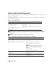
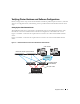
Figure 1-2. Hardware Connections for a SAN-Attached Fibre Channel Cluster
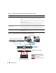
Table 1-4. Hardware Interconnections for a Direct-Attached Fibre Channel Cluster
Cluster Component Connections
Each PowerEdge system node One Cat5e/6 cable from public NIC to LAN
One Cat5e/6 cable from private Gigabit NIC to Gigabit Ethernet
switch
One Cat5e/6 cable from redundant private Gigabit NIC to redundant
Gigabit Ethernet switch
One optical cable from optical HBA 0 to the first storage system SP
and one optical cable from HBA 1 to the remaining storage SP
Each Dell | EMC Fibre Channel
storage system
Two Cat5e/6 cables connected to LAN
One to four optical connections to each Dell|EMC storage system
See "Cabling Your Storage System" for more information.
Each Gigabit Ethernet switch One Cat5e/6 connection to the private Gigabit NIC on each
PowerEdge system
Dell | EMC AX100 or CX300
Fibre Channel storage systems
public network
PowerEdge systems
(Oracle database)
Gb Ethernet switches (private network)
Dell | EMC Fibre Channel switches
(SAN)
LAN/WAN
Cat5e/6 (integrated NIC)
Cat5e/6 (copper Gigabit NIC)
fiber optic cables
additional fiber optic cables