
Owner's Manual


Deployment Guide 13
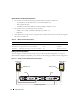
Direct-Attached Configuration
To configure your nodes in a direct-attached configuration (see Figure 1-3), perform the following steps:
1
Connect one optical cable from HBA0 on node 1 to port 0 of SP-A.
2
Connect one optical cable from HBA1 on node 1 to port 0 of SP-B.
3
Connect one optical cable from HBA0 on node 2 to port 1 of SP-A.
4
Connect one optical cable from HBA1 on node 2 to port 1 of SP-B.
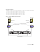
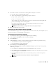
Figure 1-4. Cabling in a SAN-Attached Fibre Channel Cluster
HBA ports (2)
cluster node 1
cluster node 2
HBA ports (2)
SP-B
SP-A
sw0
sw1
01
0
1
CX3-20 storage system
FE0
FE1
FE0
FE1