
Owner's Manual


10 Deployment Guide
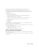
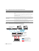
Figure 1-2. Hardware Connections for a SAN-Attached Fibre Channel Cluster
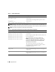
Table 1-4. Hardware Interconnections for a Direct-Attached Fibre Channel Cluster
Cluster Component Connections
Each PowerEdge system node One Cat5e/6 cable from the public NIC to the local area network (LAN)
One Cat5e/6 cable from the private Gigabit NIC to the Gigabit Ethernet
switch
One Cat5e/6 cable from the redundant private Gigabit NIC to the redundant
Gigabit Ethernet switch
One optical cable from optical HBA 0 to the first storage system storage
processor (SP) and one optical cable from HBA 1 to the remaining storage SP
Each Dell|EMC Fibre Channel
storage system
Two Cat5e/6 cables connected to the LAN
One optical connection from each SP to one HBA on each PowerEdge node
See "Cabling Your Storage System" for more information.
Each Gigabit Ethernet switch One Cat5e/6 connection to the private Gigabit NIC on each PowerEdge system
One Cat5e/6 connection to the other Gigabit Ethernet switch
Dell|EMC CX300/CX500/CX3-20
Fibre Channel storage systems
public network
PowerEdge systems
(Oracle Database)
Gigabit Ethernet switches
(private network)
Dell|EMC Fibre Channel
switches (SAN)
LAN/WAN
Cat5e/6 (integrated NIC)
Cat5e/6 (copper Gigabit NIC)
fiber optic cables
additional fiber optic cables