
Owner's Manual


iSCSI Cluster Setup for the PowerVault Enclosure 37
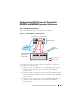
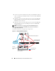
To configure your nodes in a switched configuration, see Figure 5-2, and
complete the following steps:
1
Connect one CAT 5e/6 cable from a port (iSCSI HBA or NIC) of node 1 to
the port of network switch 1.
2
Connect one CAT 5e/6 cable from a port (iSCSI HBA or NIC) of node 1 to
the port of network switch 2.
3
Connect one CAT 5e/6 cable from a port (iSCSI HBA or NIC) of node 2 to
the port of network switch 1.
4
Connect one CAT 5e/6 cable from a port (iSCSI HBA or NIC) of node 2 to
the port of network switch 2.
5
Connect one CAT 5e/6 cable from a port of switch 1 to the
In-0
port of
RAID controller
0 in the PowerVault MD3000i storage enclosure.
6
Connect one CAT 5e/6 cable from the other port of switch 1 to the
In-0
port of RAID controller
1 in the PowerVault MD3000i storage enclosure.
7
Connect one CAT 5e/6 cable from a port of switch 2 to the
In-1
port of
RAID controller
0 in the PowerVault MD3000i storage enclosure.
8
Connect one CAT 5e/6 cable from the other port of switch 2 to the
In-1
port of RAID controller
1 in the PowerVault MD3000i storage enclosure.
9
(
Optional
). Connect two SAS cables from the two PowerVault MD3000i
storage enclosures out ports to the two In ports of the first PowerVault
MD1000 expansion enclosure.
10
(
Optional
). Connect two SAS cables from the two PowerVault MD3000
storage enclosures out ports to the
In-0
ports of the second PowerVault
MD1000 expansion enclosure.
NOTE: For information on configuring the PowerVault MD1000 expansion
enclosure, see the PowerVault MD3000i storage system documentation at
suport.dell.com/manuals. It is recommended that you use
a separate network for
the iSCSI storage infrastructure. If a separate network cannot be dedicated for
iSCSI, assign the storage function to a separate virtual local area network (VLAN);
this action creates independent logical networks within a physical network.