
Owner's Manual

10 Deployment Guide
Verify that the following tasks have been completed for your cluster:
• All hardware is installed in the rack.
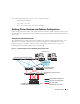
• All hardware interconnections are configured as shown in Figure 1-1 and listed in Table 1-4.
• All logical unit numbers (LUNs), Redundant array of inexpensive disks (RAID) groups, and storage
groups are created on the Dell|EMC Fibre Channel storage system.
• Storage groups are assigned to the cluster nodes.
NOTICE: Before you perform the procedures in the following sections, ensure that the system hardware and cable
connections are installed correctly.
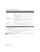
Table 1-4. Fibre Channel Hardware Interconnections
Cluster Component Connections
Each PowerEdge system node One CAT 5e/6 cable from public NIC to the local area network (LAN)
One CAT 5e/6 cable from private Gigabit NIC to Gigabit Ethernet switch (private
network)
One CAT 5e/6 cable from redundant private Gigabit NIC to redundant Gigabit
Ethernet switch (private network)
One optical cable from optical HBA 0 to Fibre Channel switch 0 and one optical
cable from HBA 1 to switch 1
Each Dell|EMC Fibre
Channel storage system
Two CAT 5e/6 cables connected to LAN (from each storage processor (SP)).
One to four optical connections to each Fibre Channel switch in a SAN-attached or
direct-attached configuration.
See "Cabling Your Storage System for a SAN-Attached Configuration" for more
information.
Each Dell|EMC Fibre
Channel switch
One optical connection from each SP to one HBA on each PowerEdge node.
One optical connection to each PowerEdge system’s HBA
Each Gigabit Ethernet switch One Cat 5e/6 connection to the private Gigabit NIC on each PowerEdge system
One Cat 5e/6 connection to the other Gigabit Ethernet switch