
Owner's Manual


10 Deployment Guide
www.dell.com | support.dell.com
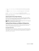
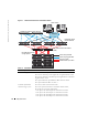
Figure 1-1. Hardware Connections for a Fibre Channel Cluster
Table 1-4. Fibre Channel Hardware Interconnections
Cluster Component Connections
Each PowerEdge system node One CAT 5e cable from public NIC to LAN
One CAT 5e cable from private Gigabit NIC to Gigabit Ethernet switch
One CAT 5e cable from a redundant private Gigabit NIC to a redundant
Gigabit Ethernet switch
One optical cable from optical HBA 0 to Fibre Channel switch 0
One optical cable from HBA 1 to switch 1
Each Dell | EMC Fibre
Channel storage system
Two CAT 5e cables connected to the LAN
One to four optical connections to each Fibre Channel switch;
for example, for a four-port configuration:
• One optical cable from SPA port 0 to Fibre Channel switch 0
• One optical cable from SPA port 1 to Fibre Channel switch 1
• One optical cable from SPB port 0 to Fibre Channel switch 1
• One optical cable from SPB port 1 to Fibre Channel switch 0
Dell | EMC Fibre Channel
storage systems
public network
PowerEdge systems
(Oracle database)
Gb Ethernet switches (private network)
Dell | EMC Fibre Channel switches
(SAN)
LAN/WAN
CAT 5e (integrated NIC)
CAT 5e (copper gigabit NIC)
fiber optic cables
additional fiber optic cables