
Owner's Manual

Deployment Guide 11
Verify that the following tasks are completed for your cluster:
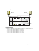
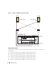
• All hardware is installed in the rack.
• All hardware interconnections are set up as shown in Figure 1-1 and
Figure 1-3, and
listed in Table 1-4.
• All logical unit numbers (LUNs), redundant array of independent disk (RAID) groups, and storage
groups are created on the Dell|EMC Fibre Channel storage system.
• Storage groups are assigned to the nodes in the cluster.
Before continuing with the following sections, visually inspect all hardware and interconnections for
correct installation.
Table 1-4. Fibre Channel Hardware Interconnections
Cluster Component Connections
Each PowerEdge system node One Category 5 enhanced (CAT 5e) or CAT 6 cable from public NIC to local area
network (LAN)
One CAT 5e or CAT 6 cable from private Gigabit NIC to Gigabit Ethernet switch
One CAT 5e or CAT 6 cable from a redundant private Gigabit NIC to a redundant
Gigabit Ethernet switch
One fiber optic cable from optical HBA 0 to Fibre Channel switch 0
One fiber optic cable from HBA 1 to switch 1
Each Dell|EMC Fibre
Channel storage system
Two CAT 5e or CAT 6 cables connected to the LAN
One to four fiber optic cable connections to each Fibre Channel switch; for
example, for a four-port configuration:
•One
fiber optic cable
from SPA port 0 to Fibre Channel switch 0
•One
fiber optic cable
from SPA port 1 to Fibre Channel switch 1
•One
fiber optic cable
from SPB port 0 to Fibre Channel switch 1
•One
fiber optic cable
from SPB port 1 to Fibre Channel switch 0
Each Dell|EMC Fibre
Channel switch
One to four fiber optic cable connections to the Dell|EMC Fibre Channel storage
system
One fiber optic cable connection to each PowerEdge system’s HBA
Each Gigabit Ethernet switch One CAT 5e or CAT 6 connection to the private Gigabit NIC on each PowerEdge
system
One CAT 5e or CAT 6 connection to the remaining Gigabit Ethernet switch