
Reference Guide

Storage Management 4.4
Deleted Alerts None
Modified Alerts Alert severity changed for 1151 and 1351
Storage Management 3.2
Product Versions to which changes apply
Storage Management 3.2.0
Server Administrator 6.2.0
New Alerts
2387, 2388, 2389, 2390, 2392, 2393
Deleted Alerts None
Modified Alerts None
Messages Not Described in This Guide
This guide describes only event messages logged by Server Administrator and Storage Management that are displayed in the Server
Administrator alert log. For information on other messages generated by your system, see one of the following sources:
• The Installation and Troubleshooting Guide or Hardware Owner's Manual shipped with your system
• Operating system documentation
• Application program documentation
Understanding Event Messages
Add your section content here.This section describes the various types of event messages generated by the Server Administrator. When
an event occurs on your system, Server Administrator sends information about one of the following event types to the systems
management console:
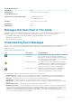
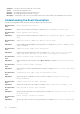
Table 2. Understanding Event Messages
Icon Alert Severity Component Status
OK /Normal /
Informational
An event that describes the successful operation of a unit. The
alert is provided for informational purposes and does not
indicate an error condition. For example, the alert may indicate
the normal start or stop of an operation, such as power supply
or a sensor reading returning to normal.
Warning / Non-critical An event that is not necessarily significant, but may indicate a
possible future problem. For example, a Warning/Non-critical
alert may indicate that a component (such as a temperature
probe in an enclosure) has crossed a warning threshold.
Critical / Failure / Error A significant event that indicates actual or imminent loss of
data or loss of function. For example, crossing a failure
threshold or a hardware failure such as an array disk.
Server Administrator generates events based on status changes in the following sensors:
• Temperature Sensor — Helps protect critical components by alerting the systems management console when temperatures
become too high inside a chassis; also monitors the temperature in a variety of locations in the chassis and in attached system(s).
• Fan Sensor — Monitors fans in various locations in the chassis and in attached system(s).
• Voltage Sensor — Monitors voltages across critical components in various chassis locations and in attached system(s).
• Current Sensor — Monitors the current (or amperage) output from the power supply (or supplies) in the chassis and in attached
system(s).
• Chassis Intrusion Sensor — Monitors intrusion into the chassis and attached system(s).
• Redundancy Unit Sensor — Monitors redundant units (critical units such as fans, AC power cords, or power supplies) within the
chassis; also monitors the chassis and attached system(s). For example, redundancy allows a second or nth fan to keep the chassis
components at a safe temperature when another fan has failed. Redundancy is normal when the intended number of critical
components are operating. Redundancy is degraded when a component fails, but others are still operating. Redundancy is lost when
there is one less critical redundancy device than required.
Introduction
17