
Reference Guide

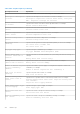
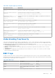
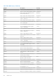
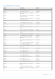
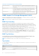
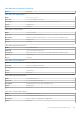
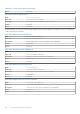
Table Of Contents
- Dell EMC OpenManage SNMP Reference Guide Version 10.1.0.0
- Contents
- Introduction
- What is new in this release
- Supported SNMP Versions
- Managed Object Used in This Document
- Server Administrator Instrumentation MIB
- Server Administrator Baseboard Management Controller, ASF MIB
- Server Administrator Storage Management MIB
- Server Administrator Field Replaceable Unit MIB
- Server Administrator Change Management MIB
- Basic Terminology
- Frequently Used Terms in Variable Names
- Tables
- Section Organization
- Other Documents You May Need
- Introduction to the Server Administrator SNMP Subagent
- System Battery Table
- Amperage Probe Table
- Power Unit Group
- Power Supply Table
- Power Usage Table
- Voltage Probe Table
- System Information Group
- Server Administrator Group
- Instrumentation MIB Version Group
- Systems Management Software Group
- System State Group
- Chassis Information Group
- Operating System Group
- System Resource Group
- Power Group
- Thermal Group
- Remote Flash BIOS Group
- Port Group
- Device Group
- Device Tables
- Pointing Device Table
- Keyboard Device Table
- Processor Device Table
- Processor Device Status Table
- Cache Device Table
- Memory Device Table
- Memory Device Mapped Address Table
- Generic Device Table
- PCI Device Table
- PCI Device Configuration Space Table
- Network Device Table
- Managed System Services Device Table
- SD Card Unit Table
- SD Card Device Table
- Device Group Variable Values
- Device Tables
- Slot Group
- Memory Group
- BIOS Setup Control Group
- Local Response Agent Group
- Cost of Ownership Group
- Cluster Group
- Baseboard Management Controller Group
- Field Replaceable Unit Group
- Storage Management Group
- Storage Management Group
- Storage Management Information Group
- Global Data Group
- Physical Devices Group
- Controller Table
- Channel Table
- Enclosure Table
- Array Disk Table
- Array Disk Enclosure Connection Table
- Array Disk Channel Connection Table
- Fan Table
- Fan Connection Table
- Power Supply Table
- Power Supply Connection Table
- Temperature Probe Table
- Temperature Probe Connection Table
- Enclosure Management Module Table
- Enclosure Management Module Connection Table
- Battery Table
- Battery Connection Table
- Tape Drive Table
- NVME adapter table
- Logical Devices Group
- Storage Management Event Group
- Change Management Group
- SNMP Traps
- Storage Management Alert Reference
- Standard Data Type Definitions
- SNMP Sample Output

Table 1952. Trap Description (continued)
Description Line Item Explanation
Previous state was:
<State>
Specifies the previous state of the sensor, for example:
Previous state was: OK (Normal)
Processor sensor status:
<status>
Specifies the status of the processor sensor, for example:
Processor sensor status: Configuration error
Redundancy unit:
<Redundancy location in
chassis>
Specifies the location of the redundant power supply or cooling unit in the chassis, for
example:
Redundancy unit: Fan Enclosure
SD card device type: <Type
of SD card device>
Specifies the type of SD card device, for example:
SD card device type: Hypervisor
SD card state: <State of
SD card>
Specifies the state of the SD card, for example:
SD card state: Present, Failed
Sensor location: <Location
in chassis>
Specifies the location of the sensor in the specified chassis, for example:
Sensor location: CPU1
Temperature sensor value
(in degrees Celsius):
<Reading>
Specifies the temperature in degrees Celsius, for example:
Temperature sensor value (in degrees Celsius): 30
Voltage sensor value (in
Volts): <Reading>
Specifies the voltage sensor value in volts, for example:
Voltage sensor value: 1.693
Understanding Trap Severity
Traps often contain information about values recorded by probes or sensors. Probes and sensors monitor critical components
for values such as amperage, voltage, and temperature. When an event occurs on your system, the Server Administrator sends
information about one of the following event types to the system management console:
● Information/Informational—An event that describes the successful operation of a unit, such as a power supply turning on
or a sensor reading returning to normal.
● Warning — An event that is not necessarily significant, but may indicate a possible future problem, such as crossing a
warning threshold.
● Critical/Error — A significant event that indicates actual or imminent loss of data or loss of function, such as crossing a
failure threshold or a hardware failure.
BMC Traps
The BMC monitors the system for critical events by communicating with various sensors on the system board and by sending
alerts and log events when certain parameters exceed their preset thresholds. All the traps documented in this section belong to
the MIB enterprise identified by OID 1.3.6.1.4.1.3183.1.1.1.
Table 1953. BMC Traps
TrapID Description Severity
262402 Generic Critical Fan Failure Critical
262530 Generic Critical Fan Failure Cleared Information
131330 Under-Voltage Problem (Lower Critical -
going low)
Critical
131458 Under-Voltage Problem Cleared Information
SNMP Traps 433