Dell EMC OpenManage SNMP Reference Guide Version 10.1.0.0 July 2021 Rev.
Notes, cautions, and warnings NOTE: A NOTE indicates important information that helps you make better use of your product. CAUTION: A CAUTION indicates either potential damage to hardware or loss of data and tells you how to avoid the problem. WARNING: A WARNING indicates a potential for property damage, personal injury, or death. © 2021 Dell Inc. or its subsidiaries. All rights reserved. Dell, EMC, and other trademarks are trademarks of Dell Inc. or its subsidiaries.
Contents Chapter 1: Introduction................................................................................................................. 7 What is new in this release................................................................................................................................................ 7 Supported SNMP Versions...............................................................................................................................................
System Resource Group Variable Values............................................................................................................. 104 Power Group.....................................................................................................................................................................106 Power Group Tables..................................................................................................................................................
Array Disk Enclosure Connection Table...............................................................................................................375 Array Disk Channel Connection Table.................................................................................................................. 377 Fan Table..................................................................................................................................................................... 379 Fan Connection Table.......
Dell Status Data Types.................................................................................................................................................. 443 Dell Date............................................................................................................................................................................ 444 Full Dates...............................................................................................................................................
1 Introduction This reference guide provides information about the Simple Network Management Protocol (SNMP) Management Information Base (MIB) which is applicable for Dell EMC OpenManage. NOTE: This guide contains information that may also be applicable to earlier OpenManage supported platforms. This introduction is divided into two sections. The first section, Introduction to SNMP Reference Guide, explains the SNMP Reference Guide design.
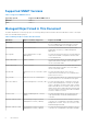
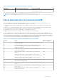
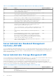
Supported SNMP Versions Table 1. Supported SNMP Versions Operating System Supported OMSA SNMP version Windows SNMP v1 Linux SNMP v1 Managed Object Used in This Document The MIB is divided into several major groups. The following table provides information about the MIB names, name of the agent that uses each MIB and the purpose: Table 2. Managed Object Used in This Document MIB Name Agent / Hardware Supported Purpose of the MIB 10892.
Table 2. Managed Object Used in This Document (continued) MIB Name Agent / Hardware Supported Purpose of the MIB Management Software. This is the v2 version of the Modular Management MIB. For further details see Release Notes for Management Information Base readme_mibs.txt. NOTE: You can download the Mibs that are listed from downloads and drivers page at Dell.com/OpenManageManuals. . Server Administrator Instrumentation MIB The Server Administrator Instrumentation MIB ( filename 10892.
Table 3.
Table 4.
Basic Terminology It is important to have a good understanding of the key technical terms used in this guide. This guide provides definitions for all essential terms used in describing the Server Administrator MIBs. For definitions on all essential terms and acronyms, see the Glossary available on the Dell Support website at dell.com/support/manuals.
Table 8. UUID Table Entry (continued) Description Defines the UUID table entry. Syntax UUIDTableEntry Access Not accessible Index uUIDIndex , uUIDchassisIndex Table 9. UUID Chassis Index Name uUIDchassisIndex Object ID 1.3.6.1.4.1.674.10892.1.300.20.1.1 Description Defines the index (one-based) of this chassis. Syntax DellObjectRange Access Read-only Table 10. UUID Index Name uUIDIndex Object ID 1.3.6.1.4.1.674.10892.1.300.20.1.
Administrator-specific variables that are used in the section. The following example shows the typical content of these four sections: 1. BIOS Setup Control Group — This section explains the purpose of the MIB group and summarizes the major features of the component groups. 2. BIOS Group Tables — If there is more than one SNMP table for a group, this section lists all of the tables. For this BIOS group example, there are eight tables listed.
● The Dell Remote Access Controller Racadm User's Guide provides information about using the racadm command line utility. ● The Dell Remote Access Controller User’s Guide provides complete information about installing and configuring a DRAC controller and using DRAC to remotely access an inoperable system. ● The Dell Update Packages User's Guide provides information about obtaining and using Dell Update Packages as part of your system update strategy.
SNMP is a systems management standard originally designed for network management. SNMP manages much more than networks. Information Technology (IT) professionals use SNMP for monitoring and managing computer systems and the various components and peripherals supported by their systems. SNMP standards are defined by the Internet Engineering Task Force (IETF). SNMP version 1 was published in August 1988 and is the most commonly supported version of SNMP.
In the preceding example, the OID prefix for the Dell enterprise would be 1.3.6.1.4.1.674. The numbers in boldface type show the categories and numbers that apply to Server Administrator. All Server Administratordefined OIDs consist of 1.3.6.1.4.1.674 followed by additional component values. SNMP Security SNMP version 1 has a very limited security mechanism. SNMP agents support the use of a community string, which is configured at each SNMP agent and is passed as a part of all SNMP request messages.
Table 14. System Battery Table Entry (continued) Description This object defines the System Battery Table Entry. Syntax StringType Access Read-only Table 15. System Battery Index Name systemBatteryIndex Object ID 1.3.6.1.4.1.674.10892.5.4.600.50.1.2 Description This attribute defines the index (one based) of the battery. Syntax ObjectRange Access Read-only Table 16. System Battery State Capabilities Name systemBatteryStateCapabilities Object ID 1.3.6.1.4.1.674.10892.5.4.600.50.1.
Table 20. System Battery Location Name (continued) Description This attribute defines the location of the battery. Syntax String64 Access Read-only Amperage Probe Table The amperage probe objects provide information about the system amperage probe in which the iDRAC resides. Table 21. Amperage Probe Chassis Index Name amperageProbechassisIndex Object ID 1.3.6.1.4.1.674.10892.5.4.600.30.1.1 Description This attribute defines the index (one based) of the system chassis.
Table 26. Amperage Probe Reading Name amperageProbeReading Object ID 1.3.6.1.4.1.674.10892.5.4.600.30.1.6 Description This attribute defines the reading for an amperage probe of type other than amperageProbeTypeIsDiscrete. When the value for amperageProbeType is amperageProbeTypeIsPowerSupplyAmps or amperageProbeTypeIsSystemAmps, the value returned for this attribute is the power usage that the probe is reading in tenths of Amps.
Table 31. Amperage Probe Upper NonCritical Threshold (continued) Description This attribute defines the upper noncritical threshold of the amperage probe. The value is an integer representing the amperage of the threshold in milliamps. Syntax Signed32BitRange Access Read-only Table 32. Amperage Probe Lower NonCritical Threshold Name amperageProbeLowerNonCriticalThreshold Object ID 1.3.6.1.4.1.674.10892.5.4.600.30.1.
Table 36. Amperage Probe Discrete Reading (continued) Syntax AmperageDiscreteReadingEnum Access Read-only Power Unit Group The Power Group objects provide information about the system power unit in which the iDRAC resides. Table 37. Power Unit Chassis Index Name powerUnitchassisIndex Object ID 1.3.6.1.4.1.674.10892.5.4.600.10.1.1 Description This attribute defines the index (one based) of the system chassis. Syntax ObjectRange Access Read-only Table 38.
Table 42. Power Supply Count For Redundancy Name powerSupplyCountForRedundancy Object ID 1.3.6.1.4.1.674.10892.5.4.600.10.1.1.6 Description This attribute defines the total number of power supplies required for this power unit to have full redundancy. Syntax ObjectRange Access Read-only Table 43. Power Unit Name Name powerUnitName Object ID 1.3.6.1.4.1.674.10892.5.4.600.10.1.1.7 Description This attribute defines the name of the power unit. Syntax String64 Access Read-only Table 44.
Table 47. Power Supply State Capabilities Unique (continued) Description This attribute defines the state capabilities of the power unit. Syntax StateCapabilitiesFlags Access Read-only Table 48. Power Supply State Settings Unique Name powerSupplyStateSettingsUnique Object ID 1.3.6.1.4.1.674.10892.5.4.600.12.1.4 Description. This attribute defines the state settings of the power supply. Syntax PowerSupplyStateSettingsUniqueFlags Access Read-only Table 49.
Table 53. Power Supply Maximum Input Voltage (continued) Object ID 1.3.6.1.4.1.674.10892.5.4.600.12.1.9 Description This attribute defines the maximum input voltage of the power supply (in Volts). Syntax Signed32BitRange Access Read-only Table 54. Power Supply power Unit Index Reference Name powerSupplypowerUnitIndexReference Object ID 1.3.6.1.4.1.674.10892.5.4.600.12 .1.10 Description This attribute defines the index to the associated power unit if the power supply is part of a power unit.
Table 58. Power Supply Rated Input Wattage (continued) Access Read-only Table 59. Power Supply FQDD Name powerSupplyFQDD Object ID 1.3.6.1.4.1.674.10892.5.4.600.12 .1.15 Description Fully qualified device descriptor (FQDD) of the power supply. Syntax FQDDString Access Read-only Table 60. Power Supply Current Input Voltage Name powerSupplyCurrentInputVoltage Object ID 1.3.6.1.4.1.674.10892.5.4.600.12 .1.
Table 64. Power Usage State Settings Name powerUsageStateSettings Object ID 1.3.6.1.4.1.674.10892.5.4.600.60.1.4 Description. This attribute defines the state settings of the power usage information. Syntax StateSettingsFlags Access Read-only Table 65. Power Usage Status Name powerUsageStatus Object ID 1.3.6.1.4.1.674.10892.5.4.600.60.1.5 Description This attribute defines the status of the power usage information. Syntax ObjectStatusEnum Access Read-only Table 66.
Table 69. Power Usage Peak Watts (continued) Syntax Unsigned32BitRange Access Read-only Table 70. Power Usage Peak Watts Start Date Name Name powerUsagePeakWattsStartDateName Object ID 1.3.6.1.4.1.674.10892.5.4.600.60.1.10 Description This attribute defines the date and time at which the data collection started for the value reported by the powerUsagePeakWatts attribute. Syntax DateName Access Read-only Table 71.
Table 75. Power Usage Idle Power Name powerUsageIdlePower Object ID 1.3.6.1.4.1.674.10892.5.4.600.60.1.15 Description This attribute defines the system idle power (in Watts). This is the minimum power the system can consume based on the current hardware configuration. Syntax Unsigned32BitRange Access Read-only Table 76. Power Usage Max Potential Power Name powerUsageMaxPotentialPower Object ID 1.3.6.1.4.1.674.10892.5.4.600.60.1.
Table 80. Power Usage Instantaneous Headroom (continued) Access Read-only Table 81. Power Usage Peak Headroom Name powerUsagePeakHeadroom Object ID 1.3.6.1.4.1.674.10892.5.4.600.60.1.21 Description This attribute defines the system peak headroom (in Watts). This is the theoretical maximum power drawn by the power supply minus peak power draw.
Table 86. Voltage Probe Status Name voltageProbeStatus Object ID 1.3.6.1.4.1.674.10892.5.4.600.20.1.5 Description This attribute defines the probe status of the voltage probe. Syntax StatusProbeEnum Access Read-only Table 87. Voltage Probe Reading Name voltageProbeReading Object ID 1.3.6.1.4.1.674.10892.5.4.600.20.1.6 Description This attribute defines the reading for a voltage probe of type other than voltageProbeTypeIsDiscrete.
Table 91. Voltage Probe Upper Critical Threshold (continued) Syntax Signed32BitRange Access Read-only Table 92. Voltage Probe Upper NonCritical Threshold Name voltageProbeUpperNonCriticalThreshold Object ID 1.3.6.1.4.1.674.10892.5.4.600.20.1.11 Description This attribute defines the upper noncritical threshold of the voltage probe. The value is an integer representing the voltage of the threshold in millivolts. Syntax Signed32BitRange Access Read-only Table 93.
Table 97. Voltage Probe Discrete Reading Name voltageProbeDiscreteReading Object ID 1.3.6.1.4.1.674.10892.5.4.600.20.1.16 Description This attribute defines the reading for a voltage probe of type voltageProbeTypeIsDiscrete. When the value for voltageProbeType is other than voltageProbeTypeIsDiscrete, a value is not returned for this attribute. When the value for voltageProbeType is voltageProbeTypeIsDiscrete, the value returned for this attribute is the discrete reading for the probe.
Table 102. System Blade Slot Number Name systemBladeSlotNumber Object ID 1.3.6.1.4.1.674.10892.5.1.3.5.0 Description This attribute defines the slot number of the blade in the chassis. Syntax StringType Access Read-only Table 103. System Operating System Name Name systemOSName Object ID 1.3.6.1.4.1.674.10892.5.1.3.6.0 Description This attribute defines the name of the operating system that the host is running. Syntax StringType Access Read-only Table 104.
Table 108. System Rack Slot Name systemRackSlot Object ID 1.3.6.1.4.1.674.10892.5.1.3.11.0 Description This attribute defines the Rack Slot locator of the system. Syntax StringType Access Read-only Table 109. System Model Name Name systemModelName Object ID 1.3.6.1.4.1.674.10892.5.1.3.12.0 Description This attribute defines the model name of the system. Syntax StringType Access Read-only Table 110. System System ID Name systemSystemID Object ID 1.3.6.1.4.1.674.10892.5.1.3.13.
Table 114. System Blade Geometry Name systemBladeGeometry Object ID 1.3.6.1.4.1.674.10892.5.1.3.17.0 Description This attribute defines the blade geometry for a blade system. (If not applicable, a 'no such name' error is returned.) Syntax BladeGeometryEnum Access Read-only Table 115. System Node ID Name systemNodeID Object ID 1.3.6.1.4.1.674.10892.5.1.3.18.0 Description This attribute defines the node ID of the system. The node ID provides a unique identifier for the system.
2 Server Administrator Group The Server Administrator group comprises of the following sections: ● ● ● ● ● ● ● ● ● ● ● ● ● ● ● ● ● ● ● Instrumentation MIB Version Group Systems Management Software Group System State Group Chassis Information Group Operating System Group System Resource Group Power Group Thermal Group Remote Flash BIOS Group Port Group Device Group Slot Group Memory Group BIOS Setup Control Group Local Response Agent Group Cost of Ownership Group Cluster Group Baseboard Management Controlle
Management Information Base Major Version Number Table 118. Management Information Base Major Version Number Name mIBMajorVersionNumber Object ID 1.3.6.1.4.1.674.10892.1.1.1.0 Description Defines the major version number of the version of this MIB supported by the systems management software. For example, if the MIB version is 1.2.3, the major version number is 1. A major version number change indicates a major change in object functionality.
NOTE: Using the Software > Server Preferences menu of Server Administrator, you can bind to either one IP address or to all IP addresses.
Table 125. Systems Management Software Supported Protocol (continued) Description Defines the systems management standards (SNMP or CIM) supported by the systems management software. Syntax SMSSupportedTypes (Systems Management Software Supported Standards) Access Read-only Table 126. Systems Management Software Preferred Protocol Name systemManagementSoftwarePreferredProtocol Object ID 1.3.6.1.4.1.674.10892.1.100.
Table 131. Systems Management Software Feature Flags (continued) Object ID 1.3.6.1.4.1.674.10892.1.100.11 Description Defines the features of the systems management software. Syntax SMSFeatureFlags (Systems Management Software Feature Flags) Access Read-only Table 132. Systems Management Software SNMP Agent Feature Flags Name systemManagementSoftwareSNMPAgentFeatureFlags Object ID 1.3.6.1.4.1.674.10892.1.100.
Table 136. Systems Management Software SNMP Agent Feature Flags Variable Name: SMSSNMPAgentFeatureFlags Data Type: Integer Possible Data Values Meaning of Data Value none(0) The Systems Management Software SNMP agent features are not enabled. supportsSparseTables(1) The SNMP agent supports sparse tables.
● systemStateBatteryStatusCombined ● systemStateSDCardUnitStatusCombined ● systemStateSDCardDeviceStatusCombined List 2 Variables that provide health status of each component in associated subsystem in chassis: ● systemStatePowerSupplyStatusDetails ● systemStateVoltageStatusDetails ● systemStateAmperageStatusDetails ● systemStateCoolingDeviceStatusDetails ● systemStateTemperatureStatusDetails ● systemStateMemoryDeviceStatusDetails ● systemStateChassisIntrusionStatusDetails ● systemStateACPowerCordStatusDet
Table 139. System State Chassis Index (continued) Access Read-only Table 140. System State Global System Status Name systemStateGlobalSystemStatus Object ID 1.3.6.1.4.1.674.10892.1.200.10.1.2 Description Defines the global system status of all chassis being monitored by this instrumentation instance. Syntax DellStatus Access Read-only Table 141. System State Chassis State Name systemStateChassisState Object ID 1.3.6.1.4.1.674.10892.1.200.10.1.
Table 145. System State Power Unit Status Details (continued) Object ID 1.3.6.1.4.1.674.10892.1.200.10.1.7 Description Defines the status of all power units in this chassis. The results are returned as a binary octet string. Each byte of the octet string represents the status of a specific power unit. The first byte returned represents the status of the first power unit, the second byte returned represents the status of the second power unit, and so on.
Table 149. System State Voltage State Details (continued) Access Read-only Table 150. System State Voltage Status Combined Name systemStateVoltageStatusCombined Object ID 1.3.6.1.4.1.674.10892.1.200.10.1.12 Description Defines the status of all voltage probes in this chassis. Syntax DellStatus Access Read-only Table 151. System State Voltage Status Details Name systemStateVoltageStatusDetails Object ID 1.3.6.1.4.1.674.10892.1.200.10.1.
Table 155. System State Cooling Unit State Details Name statesystemStateCoolingUnitStateDetails Object ID 1.3.6.1.4.1.674.10892.1.200.10.1.17 Description Defines the state of all cooling units in this chassis. The results are returned as a binary octet string. Each byte of the octet string represents the state of a specific cooling unit. The first byte returned represents the state of the first cooling unit, the second byte returned represents the state of the second cooling unit, and so on.
Table 159. System State Cooling Device Status Combined (continued) Access Read-only Table 160. System State Cooling Device Status Details Name systemStateCoolingDeviceStatusDetails Object ID 1.3.6.1.4.1.674.10892.1.200.10.1.22 Description Defines the status of all cooling devices in this chassis. The results are returned as a binary octet string. Each byte of the octet string represents the status of a specific cooling device.
Table 164. System State Memory Device State Details (continued) memory device. The first byte returned represents the state of the first memory device, the second byte returned represents the status of the second memory device, and so on. The bytes have the same definition type as DellStateSettings. Syntax Octet String Access Read-only Table 165. System State Memory Device Status Combined Name systemStateMemoryDeviceStatusCombined Object ID 1.3.6.1.4.1.674.10892.1.200.10.1.
Table 169. System State Chassis Intrusion Status Details Name systemStateChassisIntrusionStatusDetails Object ID 1.3.6.1.4.1.674.10892.1.200.10.1.31 Description Defines the intrusion status of all intrusion detection devices in this chassis. The first byte returned represents the status of the first intrusion detection device, the second byte returned represents the status of the second intrusion detection device, and so on. Syntax Octet String Access Read-only Table 170.
Table 174. System State AC Power Cord Status Combined (continued) Object ID 1.3.6.1.4.1.674.10892.1.200.10.1.36 Description Defines the overall status of all AC power cords for any AC power switches in this chassis. Syntax DellStatus Access Read-only Table 175. System State AC Power Cord Status Details Name systemStateACPowerCordStatusDetails Object ID 1.3.6.1.4.1.674.10892.1.200.10.1.37 Description Defines the individual status of all AC power cords for any AC power switches in this chassis.
Table 179. System State Event Log Status (continued) Description Defines the overall status of this chassis (ESM) event log. Syntax DellStatus Access Read-only Table 180. System State Power Unit Status Combined Name systemStatePowerUnitStatusCombined Object ID 1.3.6.1.4.1.674.10892.1.200.10.1.42 Description Defines the combined status of all power units of this chassis. Syntax DellStatus Access Read-only Table 181.
Table 185. System State AC Power Switch Status List Name systemStateACPowerSwitchStatusList Object ID 1.3.6.1.4.1.674.10892.1.200.10.1.47 Description Lists the status of each AC power switch of this chassis. The results are returned as a binary octet string where each byte of the octet string represents the status of an AC power switch. The first byte returned represents the status of the first AC power switch, and so on. The bytes have the same definition type as DellStatus.
Table 190. System State Battery Status Combined Name systemStateBatteryStatusCombined Object ID 1.3.6.1.4.1.674.10892.1.200.10.1.52 Description Defines the combined status of all batteries of this chassis. Syntax DellStatus Access Read-only Table 191. System State Battery Status List Name systemStateBatteryStatusList Object ID 1.3.6.1.4.1.674.10892.1.200.10.1.53 Description Lists the status of each battery of this chassis.
Table 195. System State SD Card Device Status List (continued) Description Lists the status of each SD Card device of this chassis. The results are returned as a binary octet string where each byte of the octet string represents the status of a SD Card device. The first byte returned represents the status of the first SD Card device, and so on. The bytes have the same definition type as DellStatus.
Table 198. Chassis Index Chassis Information (continued) Object ID 1.3.6.1.4.1.674.10892.1.300.10.1.1 Description Defines the index (one-based) of this chassis. The first chassis is numbered one. Syntax DellObjectRange Access Read-only Table 199. Chassis State Capabilities Name chassisStateCapabilities Object ID 1.3.6.1.4.1.674.10892.1.300.10.1.2 Description Defines the capabilities of the chassis. Syntax DellStateCapabilities Access Read-only Table 200.
Table 204. Chassis Name Name chassisName Object ID 1.3.6.1.4.1.674.10892.1.300.10.1.7 Description Defines the user-assigned chassis name of the chassis. Syntax DellString Access Read-only Table 205. Chassis Manufacturer Name Name chassisManufacturerName Object ID 1.3.6.1.4.1.674.10892.1.300.10.1.8 Description Defines the manufacturer’s name for this chassis. Syntax DellString Access Read-only Table 206. Chassis Model Name Name chassisModelName Object ID 1.3.6.1.4.1.674.10892.1.300.10.
Table 210. Chassis ID Extension Name chassisIDExtension Object ID 1.3.6.1.4.1.674.10892.1.300.10.1.13 Description Defines the SMBIOS machine ID of this chassis. Syntax DellUnsigned16BitRange Access Read-only Table 211. Chassis System Class Name chassisSystemClass Object ID 1.3.6.1.4.1.674.10892.1.300.10.1.14 Description Defines the chassis class of this chassis. Syntax DellChassisSystemClass (See Chassis Type) Access Read-only Table 212.
Table 216. Chassis System Primary User Name Name chassisSystemPrimaryUserName Object ID 1.3.6.1.4.1.674.10892.1.300.10.1.19 Description Defines the user-assigned primary user name for this chassis. Syntax DellString Access Read-only Table 217. Chassis System User Phone Number Name Name chassisSystemUserPhoneNumberName Object ID 1.3.6.1.4.1.674.10892.1.300.10.1.20 Description Defines the user-assigned phone number of the primary user of the system.
Table 222. Chassis LED Control Settings Unique Name chassisLEDControlSettingsUnique Object ID 1.3.6.1.4.1.674.10892.1.300.10.1.25 Description Defines the readings and settings of the LED control hardware in the chassis. Syntax DellLEDControlSettings (See Front-Panel LED Control Settings) Access Read-only Table 223. Chassis Hard-Drive (HD) Fault Clear Control Capabilities Name chassisHDFaultClearControlCapabilities Object ID 1.3.6.1.4.1.674.10892.1.300.10.1.
Table 228. Chassis Host Control Capabilities Unique Name chassishostControlCapabilitiesUnique Object ID 1.3.6.1.4.1.674.10892.1.300.10.1.31 Description Defines the capabilities of the host control object. Syntax DellHostControlCapabilities (See Host Control Capabilities) Access Read-only Table 229. Chassis Host Control Settings Unique Name chassishostControlSettingsUnique Object ID 1.3.6.1.4.1.674.10892.1.300.10.1.32 Description Defines the current settings of the host control object.
Table 234. Chassis Allow Set Commands From SNMP Name chassisallowSETCommandsfromSNMP Object ID 1.3.6.1.4.1.674.10892.1.300.10.1.37 Description Specifies whether Simple Network Management Protocol (SNMP) Set type commands are allowed by Server Administrator. This attribute does not reflect whether SNMP Set type commands are allowed by the SNMP primary agent. Syntax DellBoolean Access Read-only Table 235.
Table 240. Chassis Reseller System ID Name chassisResellerSystemID Object ID 1.3.6.1.4.1.674.10892.1.300.10.1.43 Description Defines the chassis reseller system ID. Syntax DellUnsigned16BitRange Access Read-only Table 241. Chassis NMI Button Control Capabilities Unique Name chassisNMIButtonControlCapabilitiesUnique Object ID 1.3.6.1.4.1.674.10892.1.300.10.1.44 Description Defines the capabilities of the NMI button control function.
Table 246. Chassis Express Service Code Name Name chassisExpressServiceCodeName Object ID 1.3.6.1.4.1.674.10892.1.300.10.1.49 Description Defines the express service code of the chassis. Syntax DellString Access Read-only Table 247. Chassis Node ID Name chassisNodeIDName Object ID 1.3.6.1.4.1.674.10892.1.300.10.1.50 Description Defines the NodeID of the chassis.
Table 251. UUID Index Name uUIDIndex Object ID 1.3.6.1.4.1.674.10892.1.300.20.1.2 Description Defines the index of the UUID in a specified chassis. Syntax DellObjectRange Access Read-only Table 252. UUID Type Name uUIDType Object ID 1.3.6.1.4.1.674.10892.1.300.20.1.3 Description Defines the type of the UUID for this chassis. Syntax DellUUIDType Access Read-only Table 253. UUID Value Name uUIDValue Object ID 1.3.6.1.4.1.674.10892.1.300.20.1.
Table 255. POST Log Table Entry (continued) , postLogRecordIndex Table 256. POST Log Chassis Index Name postLogchassisIndex Object ID 1.3.6.1.4.1.674.10892.1.300.30.1.1 Description Defines the index (one-based) of this chassis. Syntax DellObjectRange Access Read-only Table 257. POST Log Record Index Name postLogRecordIndex Object ID 1.3.6.1.4.1.674.10892.1.300.30.1.2 Description Defines the record number (one-based) of the POST log.
Table 261. POST Log Format (continued) Description Defines format of the POST log. Syntax DellLogFormat (See Log Format) Access Read-only Event Log Table Table 262. Event Log Table Name eventLogTableEntry Object ID 1.3.6.1.4.1.674.10892.1.300.40 Description Defines the Event Log Table. Syntax SEQUENCE OF EventLogTableEntry Access Not accessible Table 263. Event Log Table Entry Name eventLogTableEntry Object ID 1.3.6.1.4.1.674.10892.1.300.40.
Table 266. Event Log State Capabilities Unique (continued) Description Defines the capabilities of the object that is writing the event log. Syntax DellStateCapabilitiesLogUnique Access Read-only Table 267. Event Log State Settings Unique Name eventLogStateSettingsUnique Object ID 1.3.6.1.4.1.674.10892.1.300.40.1.4 Description Defines the state settings for the object that is writing the event log. Syntax DellStateSettingsLogUnique Access Read-only Table 268.
System BIOS Table This table lists objects that define the system’s basic input/output system (BIOS). Table 272. System BIOS Table Name systemBIOSTable Object ID 1.3.6.1.4.1.674.10892.1.300.50 Description Defines the System BIOS Table. Syntax SEQUENCE OF SystemBIOSTableEntry Access Not accessible Table 273. System BIOS Table Entry Name systemBIOSTableEntry Object ID 1.3.6.1.4.1.674.10892.1.300.50.1 Description Defines the System BIOS Table entry.
Table 277. System BIOS State Settings Name systemBIOSStateSettings Object ID 1.3.6.1.4.1.674.10892.1.300.50.1.4 Description Defines the state of the system BIOS of this object. Syntax DellStateSettings Access Read-only Table 278. System BIOS Status Name systemBIOSStatus Object ID 1.3.6.1.4.1.674.10892.1.300.50.1.5 Description Defines the status of the system BIOS of this object. Syntax DellStatus Access Read-only Table 279. System BIOS Size Name systemBIOSSize Object ID 1.3.6.1.4.1.
Table 283. System BIOS Ending Address Name systemBIOSEndingAddress Object ID 1.3.6.1.4.1.674.10892.1.300.50.1.10 Description Defines the ending address of the system BIOS. A zero (0) indicates that the address is unknown. Syntax DellUnsigned64BitRange Access Read-only Table 284. System BIOS Manufacturer Name Name systemBIOSManufacturerName Object ID 1.3.6.1.4.1.674.10892.1.300.50.1.11 Description Defines the system BIOS manufacturer’s name. Syntax DellString Access Read-only Table 285.
Table 285. System BIOS Characteristics (continued) ● ● ● ● ● ● ● ● ● ● ● ● ● ● ● Syntax Bit Bit Bit Bit Bit Bit Bit Bit Bit Bit Bit Bit Bit Bit Bit 24 - Int 13h - 3.5 in / 720 KB Floppy Services are supported 25 - Int 13h - 3.5 in / 2.
Firmware Table Table 288. Firmware Table Name firmwareTable Object ID 1.3.6.1.4.1.674.10892.1.300.60 Description Defines the Firmware Table. Syntax SEQUENCE OF FirmwareTableEntry Access Not accessible Table 289. Firmware Table Entry Name firmwareTableEntry Object ID 1.3.6.1.4.1.674.10892.1.300.60.1 Description Defines the Firmware Table entry Syntax FirmwareTableEntry Access Not accessible Index firmwarechassisIndex , firmwareIndex Table 290.
Table 293. Firmware State Capabilities Name firmwareStateCapabilities Object ID 1.3.6.1.4.1.674.10892.1.300.60.1.4 Description Defines the state of the firmware and allows for the setting of the firmware. Syntax DellStateCapabilities Access Read-only Table 294. Firmware Status Name firmwareStatus Object ID 1.3.6.1.4.1.674.10892.1.300.60.1.5 Description Defines the status of the firmware. Syntax DellStateSettings Access Read-only Table 295. Firmware Size Name firmwareSize Object ID 1.
Table 299. Firmware Date Name Name firmwareDateName Object ID 1.3.6.1.4.1.674.10892.1.300.60.1.10 Description Defines the date of the firmware. Syntax DellDateName Access Read-only Table 300. Firmware Version Name Name firmwareVersionName Object ID 1.3.6.1.4.1.674.10892.1.300.60.1.11 Description Defines the version name of the firmware.
Table 303. Intrusion Chassis Index (continued) Syntax DellObjectRange Access Read-only Table 304. Intrusion Index Name intrusionIndex Object ID 1.3.6.1.4.1.674.10892.1.300.70.1.2 Description Defines the index of the intrusion objects and drive bay object in this subgroup. Syntax DellObjectRange Access Read-only Table 305. Intrusion State Capabilities Name intrusionStateCapabilities Object ID 1.3.6.1.4.1.674.10892.1.300.70.1.
Table 309. Intrusion Type (continued) Syntax DellIntrusionType Access Read-only Table 310. Intrusion Location Name Name intrusionLocationName Object ID 1.3.6.1.4.1.674.10892.1.300.70.1.8 Description This attribute defines the location of the intrusion and drive bay sensor. Syntax DellString Access Read-only Baseboard Table This table lists objects that define the baseboard of a system. Table 311. Baseboard Table Name baseBoardTable Object ID 1.3.6.1.4.1.674.10892.1.300.
Table 314. Baseboard Index (continued) Description Defines the index (one-based) of the base board. Syntax DellObjectRange Access Read-only Table 315. Baseboard State Capabilities Name baseBoardStateCapabilities Object ID 1.3.6.1.4.1.674.10892.1.300.80.1.3 Description Defines the state capabilities of the baseboard. Syntax DellStateCapabilities Access Read-only Table 316. Baseboard State Settings Name baseBoardStateSettings Object ID 1.3.6.1.4.1.674.10892.1.300.80.1.
Table 320. Baseboard Type Name (continued) Description Defines the name of the type of baseboard. Syntax DellString Access Read-only Table 321. Baseboard Location Name Name baseBoardLocationName Object ID 1.3.6.1.4.1.674.10892.1.300.80.1.9 Description Defines the location name of the baseboard. Syntax DellString Access Read-only Table 322. Baseboard Manufacturer Name Name baseBoardManufacturerName Object ID 1.3.6.1.4.1.674.10892.1.300.80.1.
Table 326. Baseboard Piece Part ID (PPID) Name (continued) Description Defines the baseboard PPID. Syntax DellString Access Read-only Table 327. Baseboard Asset Tag Name Name baseBoardAssetTagName Object ID 1.3.6.1.4.1.674.10892.1.300.80.1.15 Description Defines the baseboard asset tag name. Syntax DellString Access Read-only Table 328. Baseboard Express Service Code Name Name baseBoardExpressServiceCodeName Object ID 1.3.6.1.4.1.674.10892.1.300.80.1.
Table 330. Chassis Type (continued) tower(7) The chassis type is a tower. portable(8) The chassis type is a portable. lapTop(9) The chassis type is a laptop. noteBook(10) The chassis type is a notebook. handHeld(11) The chassis type is a handheld. dockingStation(12) The chassis type is a docking station. allInOne(13) The chassis type is an all-in-one. subNoteBook(14) The chassis type is a subnotebook. spaceSaving(15) The chassis type is a spacesaver.
Table 332. Fan Control Capabilities (continued) lowOrhighSpeedCapab The fan can be set to low or high speed. le(6) Table 333. Front-Panel LED Control Capabilities Variable Name : DellLEDControlCapabilities Data Type: Integer Possible Data Values Meaning of Data Value unknown(1) The LED control capabilities are unknown. alertOnErrorCapable The LED control can be set to alert on an error (2) condition.
Table 336. Hard-Drive Fault LED Control Settings (continued) enabled(2) The hard-drive fault LEDs’ state is disabled (offline, a binary 0 value) or enabled (online, a binary 1 value). notReady(4) The hard-drive fault LEDs’ state is not ready. reset(8) The hard-drive fault LEDs have been reset. resetAndEnable(10) The hard-drive fault LEDs have been reset and enabled. Table 337.
Table 339. Host Control Capabilities (continued) Data Type: Integer Possible Data Values Meaning of Data Value manualRebootCapabl e(1) The operator can reboot capable host. manualPowerOFFCapa ble(2) The operator can power off capable host. manualPowerCycleCa pable(4) The operator can power-cycle capable host. manualAllExceptOpe rating SystemShutdownCapa ble(7) The operator can reboot and power off capable host.
Table 340. Host Control Settings (continued) manualOperatingSys temShutdown(8) The operator can shut down the operating system on the host. manualOperatingSys temShutdownThe nPowerCycle(12) The operator can shut down the operating system on the host then power cycle machine. Table 341.
Table 343. Watchdog Timer Capabilities (continued) Data Type: Integer Possible Data Values Meaning of Data Value type1Capable(1) Watchdog timer can time in intervals from 20–480 seconds. type2Capable(2) Watchdog timer can time in 30-, 60-, 120-, and 480second intervals. type3Capable(4) Watchdog timer can time in 60-second intervals. Table 344.
Table 347. System Properties (continued) none(0) No properties. energySmart(1) The system is an Energy Smart System. Table 348. NMI Button Control Settings Variable Name : DellNMIButtonControlSettings Data Type: Integer Possible Data Values Meaning of Data Value none(0) The NMI button has no settings capabilities. unknown(1) The NMI button settings are unknown. enabled(2) The NMI button state is enabled. disabled(4) The NMI button state is disabled. Table 349.
Table 350. Chassis System Class (continued) workstationClass(3 ) The chassis system class is a workstation. serverClass(4) The chassis system class is a server. desktopClass(5) The chassis system class is a desktop. portableClass(6) The chassis system class is a portable. netPCClass(7) The chassis system class is a Net PC. storageClass(8) The chassis system class is storage. Table 351.
Table 351. Firmware Type (continued) iDRAC7(21) The firmware type is Integrated Dell Remote Access Controller 7. iDRAC8(22) The firmware type is Integrated Dell Remote Access Controller 8. iDRAC9(23) The firmware type is Integrated Dell Remote Access Controller 9. Table 352. Intrusion Reading Variable Name : DellIntrusionReading Data Type: Integer Possible Data Values Meaning of Data Value chassisNotBreached(1) The chassis is not breached and no uncleared breaches.
Table 354. Baseboard Feature Flags (continued) boardIsHotSwappabl e(16) This baseboard is hot swappable. Operating System Group The Operating System Group provides status and identifying information about a system’s operating system. Identifying information includes the name, version, service pack, and patch level of the installed operating system. Operating System Memory Table Table 355. Operating System Memory Table Name operatingSystemMemoryTable Object ID 1.3.6.1.4.1.674.10892.1.400.
Table 359. Operating System Memory State Settings (continued) Description Defines the state and allows the setting of the operating system memory. Syntax DellStateSettings Access Read-only Table 360. Operating System Memory Status Name operatingSystemMemoryStatus Object ID 1.3.6.1.4.1.674.10892.1.400.20.1.4 Description Defines the status of the operating system memory. Syntax DellStatus Access Read-only Table 361.
Table 365. Operating System Memory Total Virtual Size Name operatingSystemMemoryTotalVirtualSize Object ID 1.3.6.1.4.1.674.10892.1.400.20.1.9 Description Defines the total virtual memory size in kilobytes. Syntax DellUnsigned32BitRange Access Read-only Table 366. Operating System Memory Available Virtual Size Name operatingSystemMemoryAvailableVirtualSize Object ID 1.3.6.1.4.1.674.10892.1.400.20.1.10 Description Defines the available virtual memory size in kilobytes.
Table 368. System Resource Map Table (continued) Syntax SEQUENCE OF SystemResourceMapTableEntry Access Not accessible Table 369. System Resource Map Table Entry Name systemResourceMapTableEntry Object ID 1.3.6.1.4.1.674.10892.1.500.10.1 Description Defines the System Resource Map Table entry. Syntax SystemResourceMapTableEntry Access Not accessible Index systemResourceMapchassisIndex , systemResourceMapIndex Table 370.
Table 374. System Resource Map Status Name systemResourceMapStatus Object ID 1.3.6.1.4.1.674.10892.1.500.10.1.5 Description Defines the status of this system map. Syntax DellStatus Access Read-only Table 375. System Resource Map Type Name systemResourceMapType Object ID 1.3.6.1.4.1.674.10892.1.500.10.1.6 Description Defines the type of this system map. Syntax DellSystemResourceMapType (System Resource Map Type) Access Read-only System Resource Owner Table Table 376.
Table 379. System Resource Owner Index Name systemResourceOwnerIndex Object ID 1.3.6.1.4.1.674.10892.1.500.20.1.2 Description Defines the index of system resource owners for this chassis. Syntax DellObjectRange Access Read-only Table 380. System Resource Owner State Capabilities Name systemResourceOwnerStateCapabilities Object ID 1.3.6.1.4.1.674.10892.1.500.20.1.3 Description Defines the capabilities of this system resource owner. Syntax DellStateCapabilities Access Read-only Table 381.
Table 385. System Resource Owner Description Name Name systemResourceOwnerDescriptionName Object ID 1.3.6.1.4.1.674.10892.1.500.20.1.8 Description Defines the description name of the system resource owner. Syntax DellString Access Read-only Table 386. System Resource Owner Interface Instance Name systemResourceOwnerInterfaceInstance Object ID 1.3.6.1.4.1.674.10892.1.500.20.1.9 Description Defines the associated system resource owner interface instance in this chassis.
Table 390. System Resource I/O Port Index Name systemResourceIOPortIndex Object ID 1.3.6.1.4.1.674.10892.1.500.30.1.2 Description Defines the index (one-based) of the system resource I/O ports in this chassis. Syntax DellObjectRange Access Read-only Table 391. System Resource I/O Port State Capabilities Name systemResourceIOPortStateCapabilities Object ID 1.3.6.1.4.1.674.10892.1.500.30.1.3 Description Defines the capabilities of the system resource I/O port.
Table 396. System Resource I/O Port Starting Address Name systemResourceIOPortStartingAddress Object ID 1.3.6.1.4.1.674.10892.1.500.30.1.8 Description Defines the 64 bits of the starting address of the system resource I/O port. Syntax DellUnsigned64BitRange Access Read-only Table 397. System Resource I/O Port Ending Address Name systemResourceIOPortEndingAddress Object ID 1.3.6.1.4.1.674.10892.1.500.30.1.9 Description Defines the 64 bits of the ending address of the system resource I/O port.
Table 401. System Resource Memory Index Name systemResourceMemoryIndex Object ID 1.3.6.1.4.1.674.10892.1.500.40.1.2 Description Defines the index of system resource memory in this chassis. Syntax DellObjectRange Access Read-only Table 402. System Resource Memory State Capabilities Name systemResourceMemoryStateCapabilities Object ID 1.3.6.1.4.1.674.10892.1.500.40.1.3 Description Defines the capabilities of this system resource memory. Syntax DellObjectRange Access Read-only Table 403.
Table 407. System Resource Memory Starting Address Name systemResourceMemoryStartingAddress Object ID 1.3.6.1.4.1.674.10892.1.500.40.1.8 Description Defines the 64 bits of the starting address of the system resource memory. Syntax DellUnsigned64BitRange Access Read-only Table 408. System Resource Memory Ending Address Name systemResourceMemoryEndingAddress Object ID 1.3.6.1.4.1.674.10892.1.500.40.1.9 Description Defines the 64 bits of the ending address of the system resource memory.
Table 412. System Resource Interrupt Chassis Index Name systemResourceInterruptchassisIndex Object ID 1.3.6.1.4.1.674.10892.1.500.50.1.1 Description Defines the index (one-based) of this chassis. Syntax DellObjectRange Access Not accessible Table 413. System Resource Interrupt Index Name systemResourceInterruptIndex Object ID 1.3.6.1.4.1.674.10892.1.500.50.1.2 Description Defines the index (one-based) of this interrupt resource. Syntax DellObjectRange Access Read-only Table 414.
Table 418. System Resource Interrupt Owner Share Disposition Name systemResourceInterruptShareDisposition Object ID 1.3.6.1.4.1.674.10892.1.500.50.1.7 Description Defines the share disposition of the system resource interrupt. Syntax DellResourceShareDisposition (Resource Share Disposition) Access Read-only Table 419. System Resource Interrupt Level Name systemResourceInterruptLevel Object ID 1.3.6.1.4.1.674.10892.1.500.50.1.
Table 423. System Resource DMA Table Entry (continued) Access Not accessible Index systemResourceDMAchassisIndex , systemResourceDMAIndex Table 424. System Resource DMA Chassis Index Name systemResourceDMAchassisIndex Object ID 1.3.6.1.4.1.674.10892.1.500.60.1.1 Description Defines the index (one-based) of this chassis. Syntax DellObjectRange Access Read-only Table 425. System Resource DMA Index Name systemResourceDMAIndex Object ID 1.3.6.1.4.1.674.10892.1.500.60.1.
Table 429. System Resource DMA Owner Index Reference Name systemResourceDMAOwnerIndexReference Object ID 1.3.6.1.4.1.674.10892.1.500.60.1.6 Description Defines the index to the associated system resource owner in this chassis. Syntax DellObjectRange Access Read-only Table 430. System Resource DMA Share Disposition Name systemResourceDMAShareDisposition Object ID 1.3.6.1.4.1.674.10892.1.500.60.1.7 Description Defines the share disposition of the system resource DMA.
Table 434. System Resource Map Type (continued) other(1) The system resource map type is not one of the following: unknown(2) The system resource map type is unknown (not known or not monitored). typeOne(3) The system resource map is type 1 (one). Table 435.
Table 438. Resource Interrupt Type (continued) interruptIsLevelSensitive( The interrupt type is level sensitive. 1) interruptIsLatched(2) The interrupt type is latched. Table 439. Resource Interrupt Trigger Variable Name: DellResourceInterruptTrigger Data Type: Integer Possible Data Values Meaning of Data Value interruptIsActiveWhenLow(1 The interrupt trigger is active on a low signal. ) interruptIsActiveWhenHigh( The interrupt trigger is active on a high signal. 2) Table 440.
Power Group Tables The following management information base (MIB) tables define objects for the Power Group: ● Power Unit Table ● Power Supply Table ● Voltage Probe Table ● Amperage Probe Table ● AC Power Switch Table ● AC Power Cord Table ● Battery Table ● Power Usage Table ● Power ProfileTable Power Unit Table Table 442. Power Unit Table Name powerUnitTable Object ID 1.3.6.1.4.1.674.10892.1.600.10 Description Defines the Power Unit Table.
Table 446. Power Unit State Capabilities Name powerUnitStateCapabilities Object ID 1.3.6.1.4.1.674.10892.1.600.10.1.3 Description Defines the capabilities of the power unit. Syntax DellStateCapabilities Access Read-only Table 447. Power Unit State Settings Name powerUnitStateSettings Object ID 1.3.6.1.4.1.674.10892.1.600.10.1.4 Description Defines the state and settings of the power unit. Syntax DellStateSettings Access Read-only Table 448.
Power Supply Table Table 452. Power Supply Table Name powerSupplyTable Object ID 1.3.6.1.4.1.674.10892.1.600.12 Description Defines the Power Supply Table. Syntax PowerSupplyTableEntry Access Not accessible Table 453. Power Supply Table Entry Name powerSupplyTableEntry Object ID 1.3.6.1.4.1.674.10892.1.600.12.1 Description Defines the Power Supply Table entry. Syntax PowerSupplyTableEntry Access Not accessible Index powerSupplychassisIndex, powerSupplyIndex Table 454.
Table 457. Power Supply State Settings Unique (continued) Access Read-only Table 458. Power Supply Status Name powerSupplyStatus Object ID 1.3.6.1.4.1.674.10892.1.600.12.1.5 Description Defines the status of the power supply. Syntax DellStatus Access Read-only Table 459. Power Supply Output Watts Name powerSupplyOutputWatts Object ID 1.3.6.1.4.1.674.10892.1.600.12.1.6 Description Defines the maximum sustained output wattage of the power supply in tenths of watts.
Table 463. Power Supply Power Unit Index Reference (continued) Access Read-only Table 464. Power Supply Sensor State Name powerSupplySensorState Object ID 1.3.6.1.4.1.674.10892.1.600.12.1.11 Description Defines the state reported by the power supply sensor, and supplements the state and settings of the power supply. Syntax DellPowerSupplySensorState (Power Supply Sensor State) Access Read-only Table 465. Power Supply Configuration Error Type Name powerSupplyConfigurationErrorType Object ID 1.
Table 469. Power Supply Current Input Voltage (continued) Syntax DellSigned32BitRange Access Read-only Voltage Probe Table Table 470. Voltage Probe Table Name voltageProbeTable Object ID 1.3.6.1.4.1.674.10892.1.600.20 Description Defines the Voltage Probe Table. Syntax VoltageProbeTableEntry Access Not accessible Table 471. Voltage Probe Table Entry Name voltageProbeTableEntry Object ID 1.3.6.1.4.1.674.10892.1.600.20.1 Description Defines the Voltage Probe Table entry.
Table 475. Voltage Probe State Settings Name voltageProbeStateSettings Object ID 1.3.6.1.4.1.674.10892.1.600.20.1.4 Description Defines the state and settings of the voltage probe. Syntax DellStateSettings Access Read-only Table 476. Voltage Probe Status Name voltageProbeStatus Object ID 1.3.6.1.4.1.674.10892.1.600.20.1.5 Description Defines the status of the voltage probe. Syntax DellStatusProbe Access Read-only Table 477. Voltage Probe Reading Name voltageProbeReading Object ID 1.3.
Table 481. Voltage Probe Upper Critical Threshold Name voltageProbeUpperCriticalThreshold Object ID 1.3.6.1.4.1.674.10892.1.600.20.1.10 Description Defines the value of the voltage probe’s upper critical threshold. Syntax DellSigned32BitRange Access Read-only Table 482. Voltage Probe Upper Noncritical Threshold Name voltageProbeUpperNonCriticalThreshold Object ID 1.3.6.1.4.1.674.10892.1.600.20.1.11 Description Defines the user-assigned value of the voltage probe’s upper noncritical threshold.
Table 487. Voltage Probe Discrete Reading Name voltageProbeDiscreteReading Object ID 1.3.6.1.4.1.674.10892.1.600.20.1.16 Description Defines the reading for a voltage probe of type voltageProbeTypeIsDiscrete. When the value for voltageProbeType is other than voltageProbeTypeIsDiscrete, a value is not returned for this attribute. When the value for voltageProbeType is voltageProbeTypeIsDiscrete, the value returned for this attribute is the discrete reading for the probe.
Table 491. Amperage Probe Index (continued) Syntax DellObjectRange Access Read-only Table 492. Amperage Probe State Capabilities Name amperageProbeStateCapabilities Object ID 1.3.6.1.4.1.674.10892.1.600.30.1.3 Description Defines the capabilities of the amperage probe. Syntax DellStateCapabilities Access Read-only Table 493. Amperage Probe State Settings Name amperageProbeStateSettings Object ID 1.3.6.1.4.1.674.10892.1.600.30.1.
Table 496. Amperage Probe Type Name amperageProbeType Object ID 1.3.6.1.4.1.674.10892.1.600.30.1.7 Description Defines the type of the amperage probe. Syntax DellAmperageProbeType Access Read-only Table 497. Amperage Probe Location Name Name amperageProbeLocationName Object ID 1.3.6.1.4.1.674.10892.1.600.30.1.8 Description Defines the location name of the amperage probe in this chassis. Syntax DellString Access Read-only Table 498.
Table 502. Amperage Probe Lower Critical Threshold Name amperageProbeLowerCriticalThreshold Object ID 1.3.6.1.4.1.674.10892.1.600.30.1.13 Description Defines the value of the amperage probe’s lower critical threshold. Syntax DellSigned32BitRange Access Read-only Table 503. Amperage Probe Lower Nonrecoverable Threshold Name amperageProbeLowerNonRecoverableThreshold Object ID 1.3.6.1.4.1.674.10892.1.600.30.1.
Table 507. AC Power Switch Table Entry (continued) Object ID 1.3.6.1.4.1.674.10892.1.600.40.1 Description Defines the AC Power Switch Table entry. Syntax ACPowerSwitchTableEntry Access Not accessible Index aCPowerSwitchchassisIndex , aCPowerSwitchIndex Table 508. AC Power Switch Chassis Index Name aCPowerSwitchChassisIndex Object ID 1.3.6.1.4.1.674.10892.1.600.40.1.1 Description Defines the index (one-based) of the chassis containing this AC power switch.
Table 512. AC Power Switch Redundancy Status (continued) Syntax DellStatusRedundancy Access Read-only Table 513. AC Power Cord Count for Redundancy Name aCPowerCordCountForRedundancy Object ID 1.3.6.1.4.1.674.10892.1.600.40.1.6 Description Defines the total number of AC power cords required for this AC power switch to have redundancy. Syntax DellObjectRange Access Read-only Table 514. AC Power Switch Name Name aCPowerSwitchName Object ID 1.3.6.1.4.1.674.10892.1.600.40.1.
Table 518. AC Power Cord Table Entry Name aCPowerCordTableEntry Object ID 1.3.6.1.4.1.674.10892.1.600.42.1 Description Defines the AC Power Cord Table entry. Syntax ACPowerCordTableEntry Access Not accessible Index aCPowerCordchassisIndex , aCPowerCordIndex Table 519. AC Power Cord Chassis Index Name aCPowerCordChassisIndex Object ID 1.3.6.1.4.1.674.10892.1.600.42.1.1 Description Defines the index (one-based) of the chassis containing this AC power cord.
Table 523. AC Power Cord Status (continued) Description Defines the status of this AC power cord. Syntax DellStatus Access Read-only Table 524. AC Power Cord AC Power Switch Index Reference Name aCPowerCordaCPowerSwitchIndexReference Object ID 1.3.6.1.4.1.674.10892.1.600.42.1.6 Description Defines the index (one-based) to the associated AC power switch for this AC power cord. Syntax DellObjectRange Access Read-only Table 525.
Table 528. Battery Chassis Index (continued) Access Read-only Table 529. Battery Index Name batteryIndex Object ID 1.3.6.1.4.1.674.10892.1.600.50.1.2 Description Defines the index (one-based) of the battery. Syntax DellObjectRange Access Read-only Table 530. Battery State Capabilities Name batteryStateCapabilities Object ID 1.3.6.1.4.1.674.10892.1.600.50.1.3 Description Defines the state capabilities of the battery. Syntax DellStateCapabilities Access Read-only Table 531.
Table 534. Battery Location Name (continued) Access Read-only Power Usage Table Table 535. Power Usage Table Name powerUsageTable Object ID 1.3.6.1.4.1.674.10892.1.600.60 Description Defines the Power Usage Table. Syntax SEQUENCE OF PowerUsageTableEntry Access Not accessible Table 536. Power Usage Table Entry Name powerUsageTableEntry Object ID 1.3.6.1.4.1.674.10892.1.600.60.1 Description Defines the Power Usage Table Entry.
Table 540. Power Usage State Settings (continued) Object ID 1.3.6.1.4.1.674.10892.1.600.60.1.4 Description Defines the state settings of the power usage information. Syntax DellStateSettings Access Read-only Table 541. Power Usage Status Name powerUsageStatus Object ID 1.3.6.1.4.1.674.10892.1.600.60.1.5 Description Defines the status of the power usage information. Syntax DellStatus Access Read-only Table 542. Power Usage Entity Name Name powerUsageEntityName Object ID 1.3.6.1.4.1.674.
Table 546. Power Usage Peak Watts Start Date Name Name powerUsagePeakWattsStartDateName Object ID 1.3.6.1.4.1.674.10892.1.600.60.1.10 Description Defines the date and time at which the data collection started for the value reported by the powerUsagePeakWatts attribute. Syntax DellDateName Access Read-only Table 547. Power Usage Peak Watts Reading Date Name Name powerUsagePeakWattsReadingDateName Object ID 1.3.6.1.4.1.674.10892.1.600.60.1.
Table 551. Power Usage Idle Power (continued) Syntax DellUnsigned32BitRange Access Read-only Table 552. Power Usage Max Potential Power Name powerUsageMaxPotentialPower Object ID 1.3.6.1.4.1.674.10892.1.600.60.1.16 Description Defines the maximum potential power (in Watts) of the system. This is the maximum power the system can consume based on the current hardware configuration. Syntax DellUnsigned32BitRange Access Read-only Table 553.
Table 557. Power Usage Peak Headroom (continued) Description Defines the system peak headroom (in Watts). This is the theoretical maximum power drawn by the power supply minus peak power draw. Syntax DellUnsigned32BitRange Access Read-only Power Profile Table Table 558. Power Profile Table Name powerProfileTable Object ID 1.3.6.1.4.1.674.10892.1.600.70 Description Defines the Power Profile Table. Syntax SEQUENCE OF PowerProfileTableEntry Access Not accessible Table 559.
Table 562. Power Profile Supported Profiles (continued) Access Read-only Table 563. Power Profile Setting Name powerProfileSetting Object ID 1.3.6.1.4.1.674.10892.1.600.70.1.4 Description Defines the power profile setting. Syntax DellPowerProfileType Access Read-only Table 564. Power Profile Custom CPU Management Capabilities Name powerProfileCustomCPUManagementCapabilities Object ID 1.3.6.1.4.1.674.10892.1.600.70.1.
Table 568. Power Profile Custom Fan Management Capabilities (continued) Object ID 1.3.6.1.4.1.674.10892.1.600.70.1.9 Description Defines the custom fan power and performance management capabilities that are available for the Custom power profile. Syntax DellFanPowerPerformanceManagementType Access Read-only Table 569. Power Profile Custom Fan Management Setting Name powerProfileCustomFanManagementSetting Object ID 1.3.6.1.4.1.674.10892.1.600.70.1.
Table 571. Power Supply State Settings Unique (continued) acPowerIsON(128) The power supply is indicating that the AC power is on. onlineAndAcPowerIsON (130) The power supply is online and indicating that the AC power is on. onlineAndPredictiveFail ure(210) The power supply is online and indicating that it has a problem. acPowerAndSwitchAreOn PowerSupplyIsOnIsOkAnd Online(242) The power supply is online and OK. Table 572.
Table 574. Power Supply Configuration Error Type (continued) vendorMismatch(1) The power supply configuration error type is vendor mismatch. revisionMismatch(2) The power supply configuration error type is revision mismatch. processorMissing(3) The power supply configuration error type is processor missing. Table 575.
Table 577. Amperage Probe Definitions (continued) amperageProbeTypeIsOther(1) The amperage probe type is not one of the following: amperageProbeTypeIsUnknown(2) The amperage probe type is unknown (not known or not monitored). amperageProbeTypeIs1Point5Volt(3) The amperage probe type is a 1.5-ampere (A) probe. amperageProbeTypeIs3Point3volt(4) The amperage probe type is a 3.3-A probe. amperageProbeTypeIs5Volt(5) The amperage probe type is a 5-A probe.
Table 579. AC Power Switch Capabilities (continued) inputSourceCord1ReturnCapable(4) Input source is AC power cord 1, with return. inputSourceCord2NoReturnCapable(8) Input source is AC power cord 2, with no return. inputSourceCord2ReturnCapable(16) Input source is AC power cord 2, with return. inputSourceSharedCapable(32) Input source is shared. Table 580.
Table 583. AC Power Cord State Settings (continued) acPowerCordIsActive Source(16) The AC power cord is the active source of AC power. Table 584. Battery Reading Variable Name: DellBatteryReading Data Type: Integer NOTE: These values are bit masks, so combination values are possible. Possible Data Values Meaning of Data Value predictiveFailure(1) Battery sensor detects predictive failure. failed(2) Battery has failed. presenceDetected(4) Battery presence is detected. Table 585.
Table 588. CPU Power Performance Management Type (continued) NOTE: These values are bit masks, so combination values are possible. Possible Data Values Meaning of Data Value maxPerformance(1) CPU power and performance management type is Maximum Performance. minPower(2) CPU power and performance management type is Minimum Power. osDBPM(4) CPU power and performance management type is OS Demand Based Power Management.
Thermal Group Tables The following management information base (MIB) tables define the objects in the Thermal Group: ● Cooling Unit Table ● Cooling Device Table ● Temperature Probe Table Cooling Unit Table Table 591. Cooling Unit Table Name coolingUnitTable Object ID 1.3.6.1.4.1.674.10892.1.700.10 Description Defines the Cooling Unit Table. Syntax TableEntry Access Not accessible Table 592. Cooling Unit Table Entry Name coolingUnitTableEntry Object ID 1.3.6.1.4.1.674.10892.1.700.10.
Table 595. Cooling Unit State Capabilities (continued) Object ID 1.3.6.1.4.1.674.10892.1.700.10.1.3 Description Defines the capabilities of the cooling unit. Syntax DellStateCapabilities Access Read-only Table 596. Cooling Unit State Settings Name coolingUnitStateSettings Object ID 1.3.6.1.4.1.674.10892.1.700.10.1.4 Description Defines the state and settings of the cooling unit. Syntax DellStateSettings Access Read-only Table 597.
Cooling Device Table Table 601. Cooling Device Table Name coolingDeviceTable Object ID 1.3.6.1.4.1.674.10892.1.700.12 Description Defines the Cooling Device Table. Syntax CoolingDeviceTableEntry Access Not accessible Table 602. Cooling Device Table Entry Name coolingDeviceTableEntry Object ID 1.3.6.1.4.1.674.10892.1.700.12.1 Description Defines the Cooling Device Table entry.
Table 606. Cooling Device State Settings Name coolingDeviceStateSettings Object ID 1.3.6.1.4.1.674.10892.1.700.12.1.4 Description Defines the state and settings of the cooling device. Syntax DellStateSettings Access Read-only Table 607. Cooling Device Status Name coolingDeviceStatus Object ID 1.3.6.1.4.1.674.10892.1.700.12.1.5 Description Defines the status of the cooling device. Syntax DellStatusProbe Access Read-only Table 608.
Table 611. Cooling Device Upper Nonrecoverable Threshold (continued) Description Defines the value of the fan’s upper nonrecoverable threshold. Syntax DellSigned32BitRange Access Read-only Table 612. Cooling Device Upper Critical Threshold Name coolingDeviceUpperCriticalThreshold Object ID 1.3.6.1.4.1.674.10892.1.700.12.1.10 Description Defines the value of the fan’s upper critical threshold. Syntax DellSigned32BitRange Access Read-only Table 613.
Table 617. Cooling Device Cooling Unit Index Reference (continued) Description Defines the index for the associated system cooling unit in this chassis. Syntax DellObjectRange Access Read-only Table 618. Cooling Device Subtype Name coolingDeviceSubType Object ID 1.3.6.1.4.1.674.10892.1.700.12.1.16 Description Defines the cooling device subtype. Syntax DellCoolingDeviceSubType (Cooling Device Subtype) Access Read-only Table 619.
Table 622. Temperature Probe Table Entry (continued) Syntax TemperatureProbeTableEntry Access Not accessible Index temperatureProbechassisIndex , temperatureProbeIndex Table 623. Temperature Probe Chassis Index Name temperatureProbechassisIndex Object ID 1.3.6.1.4.1.674.10892.1.700.20.1.1 Description Defines the index (one-based) of this chassis. Syntax DellObjectRange Access Read-only Table 624. Temperature Probe Index Name temperatureProbeIndex Object ID 1.3.6.1.4.1.674.10892.1.700.20.
Table 628. Temperature Probe Reading Name temperatureProbeReading Object ID 1.3.6.1.4.1.674.10892.1.700.20.1.6 Description Defines the value of the temperature probe. When the value for temperatureProbeType is other than temperatureProbeTypeIsDiscrete, the value returned for this attribute is the temperature that the probe is reading in tenths of degrees Centigrade. When the value for temperatureProbeType is temperatureProbeTypeIsDiscrete, a value is not returned for this attribute.
Table 633. Temperature Probe Upper Noncritical Threshold (continued) Syntax DellSigned32BitRange Access Read-only Table 634. Temperature Probe Lower Noncritical Threshold Name temperatureProbeLowerNonCriticalThreshold Object ID 1.3.6.1.4.1.674.10892.1.700.20.1.12 Description Defines the user-assigned value of the temperature probe’s lower noncritical threshold. Syntax DellSigned32BitRange Access Read-only Table 635.
Thermal Group Variable Values This section includes definitions for server administrator-specific variable values used in this section. Table 639. Cooling Device Type Variable Name: DellCoolingDeviceType Data Type: Integer Possible Data Values Meaning of Data Value coolingDeviceTypeIsOther(1) The cooling device type is not one of the following: coolingDeviceTypeIsUnknown(2) The cooling device type is unknown (not known or not monitored). coolingDeviceTypeIsAFan(3) The cooling device type is a fan.
Table 642. Temperature Probe Type Variable Name: DellTemperatureProbeType Data Type: Integer Possible Data Values Meaning of Data Value temperatureProbeTypeIsOther(1) The temperature probe subtype is not one of the following: temperatureProbeTypeIsUnknown(2) The temperature probe subtype is unknown (not known or not monitored). temperatureProbeTypeIsAmbientESM(3) The temperature probe is for ambient Embedded Systems Management (ESM).
Table 645. Remote Flash BIOS Table Entry (continued) Access Not accessible Index remoteFlashBIOSchassisIndex, remoteFlashBIOSIndex Table 646. Remote Flash BIOS Chassis Index Name remoteFlashBIOSchassisIndex Object ID 1.3.6.1.4.1.674.10892.1.900.10.1.1 Description Defines the index (one-based) of this chassis. Syntax DellObjectRange Access Read-only Table 647. Remote Flash BIOS Index Name remoteFlashBIOSIndex Object ID 1.3.6.1.4.1.674.10892.1.900.10.1.
Table 651. Remote Flash BIOS Last BIOS Date Name (continued) Description Defines the date of the last BIOS update. Syntax DellDateName Access Read-only Table 652. Remote Flash BIOS Completion Code Name remoteFlashBIOSCompletionCode Object ID 1.3.6.1.4.1.674.10892.1.900.10.1.7 Description Defines the completion code of the last BIOS update. Syntax DellRemoteFlashBIOSCompletionCode (Remote Flash BIOS Completion Code) Access Read-only Table 653.
Table 655. Remote Flash BIOS State Settings (continued) canceled(8) The remote flash BIOS has been canceled. pending(16) The remote flash BIOS update is pending. other(32) The remote flash BIOS state/setting is not one of the previous values. Table 656.
● Serial Port Table ● Universal Serial Bus (USB) Port Table Pointing Port Table Table 657. Pointing Port Table Name pointingPortTable Object ID 1.3.6.1.4.1.674.10892.1.1000.10 Description Defines the Pointing Port Table. Syntax IntegerPointingPortTableEntry Access Not accessible Table 658. Pointing Port Table Entry Name pointingPortTableEntry Object ID 1.3.6.1.4.1.674.10892.1.1000.10.1 Description Defines the Pointing Port Table entry.
Table 661. Pointing Port State Capabilities (continued) Access Read-only Table 662. Pointing Port State Settings Name pointingPortStateSettings Object ID 1.3.6.1.4.1.674.10892.1.1000.10.4 Description Defines the state and settings of the pointing port. Syntax DellStateSettings Access Read-only Table 663. Pointing Port Status Name pointingPortStatus Object ID 1.3.6.1.4.1.674.10892.1.1000.10.5 Description Defines the status of the pointing port.
Table 667. Pointing Port BIOS Connector Type (continued) Access Read-only Keyboard Port Table Table 668. Keyboard Port Table Name keyboardPortTable Object ID 1.3.6.1.4.1.674.10892.1.1000.20 Description Defines the Keyboard Port Table. Syntax IntegerKeyboardPortTableEntry Access Not accessible Table 669. Keyboard Port Table Entry Name keyboardPortTableEntry Object ID 1.3.6.1.4.1.674.10892.1.1000.20.1 Description Defines the Keyboard Port Table entry.
Table 672. Keyboard Port State Capabilities (continued) Access Read-only Table 673. Keyboard Port State Settings Name keyboardPortStateSettings Object ID 1.3.6.1.4.1.674.10892.1.1000.20.1.4 Description Defines the state and settings of the keyboard port. Syntax DellStateSettings Access Read-only Table 674. Keyboard Port Status Name keyboardPortStatus Object ID 1.3.6.1.4.1.674.10892.1.1000.20.1.5 Description Defines the status of the keyboard port.
Table 678. Keyboard Port BIOS Connector Type (continued) Access Read-only Processor Port Table Table 679. Processor Port Table Name processorPortTable Object ID 1.3.6.1.4.1.674.10892.1.1000.30 Description Defines the Processor Port Table. Syntax IntegerProcessorPortTableEntry Access Not accessible Table 680. Processor Port Table Entry Name processorPortTableEntry Object ID 1.3.6.1.4.1.674.10892.1.1000.30.1 Description Defines the Processor Port Table entry.
Table 683. Processor Port State Capabilities (continued) Access Read-only Table 684. Processor Port State Settings Name processorPortStateSettings Object ID 1.3.6.1.4.1.674.10892.1.1000.30.1.4 Description Defines the state and settings of the processor port. Syntax DellStateSettings Access Read-only Table 685. Processor Port Status Name processorPortStatus Object ID 1.3.6.1.4.1.674.10892.1.1000.30.1.5 Description Defines the status of the processor port.
Table 689. Processor Port BIOS Connector Type (continued) Access Read-only Memory Device Port Table Table 690. Memory Device Port Table Name memoryDevicePortTable Object ID 1.3.6.1.4.1.674.10892.1.1000.40 Description Defines the Memory Device Port Table. Syntax IntegerMemoryDevicePortTableEntry Access Not accessible Table 691. Memory Device Port Table Entry Name memoryDevicePortTableEntry Object ID 1.3.6.1.4.1.674.10892.1.1000.40.1 Description Defines the Memory Device Port Table entry.
Table 694. Memory Device Port State Capabilities (continued) Access Read-only Table 695. Memory Device Port State Settings Name memoryDevicePortStateSettings Object ID 1.3.6.1.4.1.674.10892.1.1000.40.1.4 Description Defines the state and settings of the memory device port. Syntax DellStateSettings Access Read-only Table 696. Memory Device Port Status Name memoryDevicePortStatus Object ID 1.3.6.1.4.1.674.10892.1.1000.40.1.5 Description Defines the status of the memory device port.
Table 700. Memory Device Port BIOS Connector Type (continued) Access Read-only Table 701. Memory Device Port Physical Memory Array Index Reference Name memoryDevicePortPhysicalMemoryArrayIndexReference Object ID 1.3.6.1.4.1.674.10892.1.1000.40.1.10 Description Defines the index to the associated physical memory array. Syntax DellUnsigned32BitRange Access Read-only Table 702.
Table 705. Monitor Port Chassis Index (continued) Syntax DellObjectRange Access Read-only Table 706. Monitor Port Index Name monitorPortIndex Object ID 1.3.6.1.4.1.674.10892.1.1000.50.1.2 Description Defines the index of the monitor ports in this chassis. Syntax DellObjectRange Access Read-only Table 707. Monitor Port State Capabilities Name monitorPortStateCapabilities Object ID 1.3.6.1.4.1.674.10892.1.1000.50.1.3 Description Defines the capabilities of the monitor port.
Table 711. Monitor Port Connector Type (continued) Syntax DellMonitorPortConnectorTypes (See Monitor Port Connector Types) Access Read-only Table 712. Monitor Port Name Name monitorPortName Object ID 1.3.6.1.4.1.674.10892.1.1000.50.1.8 Description Defines the name of the monitor port. Syntax DellString Access Read-only Table 713. Monitor Port BIOS Connector Type Name monitorPortBIOSConnectorType Object ID 1.3.6.1.4.1.674.10892.1.1000.50.1.
Table 716. SCSI Port Chassis Index (continued) Syntax DellObjectRange Access Read-only Table 717. SCSI Port Index Name sCSIPortIndex Object ID 1.3.6.1.4.1.674.10892.1.1000.60.1.2 Description Defines the index of the SCSI ports in this chassis. Syntax DellObjectRange Access Read-only Table 718. SCSI Port State Capabilities Name sCSIPortStateCapabilities Object ID 1.3.6.1.4.1.674.10892.1.1000.60.1.3 Description Defines the capabilities of the SCSI port.
Table 722. SCSI Port Connector Type (continued) Syntax DellSCSIPortConnectorType (See SCSI Port Connector Types) Access Read-only Table 723. SCSI Port Name Name sCSIPortName Object ID 1.3.6.1.4.1.674.10892.1.1000.60.1.8 Description Defines the name of the SCSI port. Syntax DellString Access Read-only Table 724. SCSI Port BIOS Connector Type Name sCSIPortBIOSConnectorType Object ID 1.3.6.1.4.1.674.10892.1.1000.60.1.9 Description Defines the BIOS connector type of the SCSI port.
Table 727. Parallel Port Chassis Index (continued) Syntax DellObjectRange Access Read-only Table 728. Parallel Port Index Name parallelPortIndex Object ID 1.3.6.1.4.1.674.10892.1.1000.70.1.2 Description Defines the index of the parallel ports in this chassis. Syntax DellObjectRange Access Read-only Table 729. Parallel Port State Capabilities Name parallelPortStateCapabilities Object ID 1.3.6.1.4.1.674.10892.1.1000.70.1.3 Description Defines the capabilities of the parallel port.
Table 733. Parallel Port Connector Type (continued) Syntax DellParallelPortConnectorType Access Read-only Table 734. Parallel Port Name Name parallelPortName Object ID 1.3.6.1.4.1.674.10892.1.1000.70.1.8 Description Defines the name of the parallel port. Syntax DellString Access Read-only Table 735. Parallel Port Connector Pin Out Name parallelPortConnectorPinOut Object ID 1.3.6.1.4.1.674.10892.1.1000.70.1.9 Description Defines the pinout of the parallel port.
Table 739. Parallel Port DMA Support (continued) Syntax DellBoolean Access Read-only Serial Port Table Table 740. Serial Port Name serialPortTable Object ID 1.3.6.1.4.1.674.10892.1.1000.80 Description Defines the Serial Port Table. Syntax IntegerSerialPortTableEntry Access Not accessible Table 741. Serial Port Table Entry Name serialPortTableEntry Object ID 1.3.6.1.4.1.674.10892.1.1000.80.1 Description Defines the Serial Port Table entry.
Table 744. Serial Port State Capabilities (continued) Syntax DellStateCapabilities Access Read-only Table 745. Serial Port State Settings Name serialPortStateSettings Object ID 1.3.6.1.4.1.674.10892.1.1000.80.1.4 Description Defines the state and settings of the serial port. Syntax DellStateSettings Access Read-only Table 746. Serial Port Status Name serialPortStatus Object ID 1.3.6.1.4.1.674.10892.1.1000.80.1.5 Description Defines the status of the serial port.
Table 750. Serial Port Maximum Speed (continued) Syntax DellUnsigned32BitRange Access Read-only Table 751. Serial Port Capabilities Unique Name serialPortCapabilitiesUnique Object ID 1.3.6.1.4.1.674.10892.1.1000.80.1.10 Description Defines additional capabilities of the serial port. Syntax DellSerialPortCapabilitiesUnique Access Read-only Table 752. Serial Port Base I/O Address Name serialPortBaseIOAddress Object ID 1.3.6.1.4.1.674.10892.1.1000.80.1.
Table 756. USB Port Chassis Index Name uSBPortchassisIndex Object ID 1.3.6.1.4.1.674.10892.1.1000.90.1.1 Description Defines the index (one-based) of this chassis. Syntax DellObjectRange Access Read-only Table 757. USB Port Index Name uSBPortIndex Object ID 1.3.6.1.4.1.674.10892.1.1000.90.1.2 Description Defines the index of the USB ports in this chassis Syntax DellObjectRange Access Read-only Table 758. USB Port State Capabilities Name uSBPortStateCapabilities Object ID 1.3.6.1.4.1.
Table 762. USB Port Connector Type Name uSBPortConnectorType Object ID 1.3.6.1.4.1.674.10892.1.1000.90.1.7 Description Defines the connector type of the USB port. Syntax DellUSBPortConnectorType Access Read-only Table 763. USB Port Name Name uSBPortName Object ID 1.3.6.1.4.1.674.10892.1.1000.90.1.8 Description Defines the name of the USB port.
Table 765. Keyboard Port Connector Types Variable Name : DellKeyboardPortConnectorType Data Type: Integer Possible Data Values Meaning of Data Value connectorPortTypeIsOther(1) The keyboard port connector type is not one of the following: connectorPortTypeIsUnknown(2) The keyboard port connector type is unknown. connectorPortTypeIsMiniDIN(3) The keyboard port connector type is a mini DIN. connectorPortTypeIsMicroDIN(4) The keyboard port connector type is a MicroDIN.
Table 767. Memory Device Port Connector Types (continued) connectorPortTypeIsSIMM(3) The memory device port connector type is a single in-line memory module (SIMM). connectorPortTypeIsSIP(4) The memory device port connector type is a SIP. connectorPortTypeIsAChip(5) The memory device port connector type is a chip. connectorPortTypeIsDIP(6) The memory device port connector type is a dual in-line package (DIP). connectorPortTypeIsZIP(7) The memory device port connector type is a ZIP.
Device Tables The following management information base (MIB) tables define objects in the Device Group: ● ● ● ● ● ● ● ● ● ● ● ● ● ● Pointing Device Table Keyboard Device Table Processor Device Table Processor Device Status Table Cache Device Table Memory Device Table Memory Device Mapped Address Table Generic Device Table PCI Device Table PCI Device Configuration Space Table Network Device Table Managed System Services Device Table SD Card Unit Table SD Card Device Table Pointing Device Table Table 770.
Table 773. Pointing Device Index Name pointingDeviceIndex Object ID 1.3.6.1.4.1.674.10892.1.1100.10.1.2 Description Defines the index of the pointing device in this chassis. Syntax DellObjectRange Access Read-only Table 774. Pointing Device State Capabilities Name pointingDeviceStateCapabilities Object ID 1.3.6.1.4.1.674.10892.1.1100.10.1.3 Description Defines the capabilities of the pointing device. Syntax DellStateCapabilities Access Read-only Table 775.
Table 779. Pointing Device Number of Buttons Name pointingDeviceNumberofButtons Object ID 1.3.6.1.4.1.674.10892.1.1100.10.1.8 Description Defines the number of buttons on the pointing device. Syntax DellUnsigned8BitRange Access Read-only Keyboard Device Table Table 780. Keyboard Device Table Name keyboardDeviceTableEntry Object ID 1.3.6.1.4.1.674.10892.1.1100.20 Description Defines the Keyboard Device Table. This table references the Keyboard Port Index (Keyboard Port Index).
Table 784. Keyboard Device State Capabilities Name keyboardDeviceStateCapabilities Object ID 1.3.6.1.4.1.674.10892.1.1100.20.1.3 Description Defines the capabilities of the keyboard device. Syntax DellStateCapabilities Access Read-only Table 785. Keyboard Device State Settings Name keyboardDeviceStateSettings Object ID 1.3.6.1.4.1.674.10892.1.1100.20.1.4 Description Defines the state of the keyboard device. Syntax DellStatesSettings Access Read-only Table 786.
Processor Device Table Table 790. Processor Device Table Name processorDeviceTable Object ID 1.3.6.1.4.1.674.10892.1.1100.30 Description Defines the Processor Device Table. Syntax SEQUENCE OF ProcessorDeviceTableEntry Access Not accessible Table 791. Processor Device Table Entry Name processorDeviceTableEntry Object ID 1.3.6.1.4.1.674.10892.1.1100.30.1 Description Defines the Processor Device Table entry.
Table 795. Processor Device State Settings Name processorDeviceStateSettings Object ID 1.3.6.1.4.1.674.10892.1.1100.30.1.4 Description Defines the state of the processor device. Syntax DellStateSettings Access Read-only Table 796. Processor Device Status Name processorDeviceStatus Object ID 1.3.6.1.4.1.674.10892.1.1100.30.1.5 Description Defines the status of the processor device. Syntax DellStatus Access Read-only Table 797.
Table 801. Processor Device Family Name processorDeviceFamily Object ID 1.3.6.1.4.1.674.10892.1.1100.30.1.10 Description Defines the family of the processor device. Syntax DellProcessorDeviceFamily (See Processor Device Family) Access Read-only Table 802. Processor Device Maximum Speed Name processorDeviceMaximumSpeed Object ID 1.3.6.1.4.1.674.10892.1.1100.30.1.11 Description Defines the maximum speed of the processor device in megahertz (MHz). A zero (0) indicates that the speed is unknown.
Table 806. Processor Device Upgrade Information (continued) Access Read-only Table 807. Processor Device Version Name Name processorDeviceVersionName Object ID 1.3.6.1.4.1.674.10892.1.1100.30.1.16 Description Defines the version name of the processor device. Syntax DellString Access Read-only Table 808. Processor Device Core Count Name processorDeviceCoreCount Object ID 1.3.6.1.4.1.674.10892.1.1100.30.1.17 Description Defines the number of processor cores detected for the processor device.
Table 811. Processor Device Characteristics (continued) Bit Position Meaning if Set Bit 3-15 Reserved Syntax DellUnsigned16BitRange Access Read-only Table 812. Processor Device Extended Capabilities Name processorDeviceExtendedCapabilities Object ID 1.3.6.1.4.1.674.10892.1.1100.30.1.21 Description This attribute defines extended capabilities of the processor device. This attribute is a bit field where a bit has the meaning defined below when set to 1 (one).
Table 815. Processor Device Model Name Name processorDeviceModelName Object ID 1.3.6.1.4.1.674.10892.1.1100.30.1.24 Description Defines the model of the processor device. Syntax DellString Access Read-only Table 816. Processor Device Stepping Name Name processorDeviceSteppingName Object ID 1.3.6.1.4.1.674.10892.1.1100.30.1.25 Description Defines the stepping of the processor device. Syntax DellString Access Read-only Table 817.
Table 819. Processor Device Status Table Entry (continued) Object ID 1.3.6.1.4.1.674.10892.1.1100.32.1 Description Defines the Processor Device Status Table Entry. Syntax ProcessorDeviceStatusTableEntry Access Not accessible Index processorDeviceStatusChassisIndex , processorDeviceStatusIndex Table 820. Processor Device Status Chassis Index Name processorDeviceStatusChassisIndex Object ID 1.3.6.1.4.1.674.10892.1.1100.32.1.1 Description Defines the index (one-based) of the associated chassis.
Table 824. Processor Device Status (continued) Description Defines the status of the processor device status probe. This status is joined into the processorDeviceStatus attribute. Syntax DellStatus Access Read-only Table 825. Processor Device Status Reading Name processorDeviceStatusReading Object ID 1.3.6.1.4.1.674.10892.1.1100.32.1.6 Description Defines the reading of the processor device status probe. Syntax DellProcessorDeviceStatusReading Access Read-only Table 826.
Table 829. Cache Device Table Entry (continued) Index cacheDevicechassisIndex , cacheDeviceIndex Table 830. Cache Device Chassis Index Name cacheDevicechassisIndex Object ID 1.3.6.1.4.1.674.10892.1.1100.40.1.1 Description Defines the index (one-based) of this chassis. Syntax DellObjectRange Access Read-only Table 831. Cache Device Index Name cacheDeviceIndex Object ID 1.3.6.1.4.1.674.10892.1.1100.40.1.2 Description Defines the index of the cache device in this chassis.
Table 835. Cache Device Processor Device Index Reference Name cacheDeviceprocessorDeviceIndexReference Object ID 1.3.6.1.4.1.674.10892.1.1100.40.1.6 Description Defines the index number of the processor device with which this cache device is associated. Syntax DellObjectRange Access Read-only Table 836. Cache Device Type Name cacheDeviceType Object ID 1.3.6.1.4.1.674.10892.1.1100.40.1.7 Description Defines the type of cache device.
Table 841. Cache Device Maximum Size Name cacheDeviceMaximumSize Object ID 1.3.6.1.4.1.674.10892.1.1100.40.1.12 Description Defines the maximum size of the cache device in kilobytes (KB). A zero (0) indicates that the size is unknown. Syntax DellUnsigned32BitRange Access Read-only Table 842. Cache Device Current Size Name cacheDeviceCurrentSize Object ID 1.3.6.1.4.1.674.10892.1.1100.40.1.13 Description Defines the current size of the cache device in KB.
Table 846. Cache Device Error Checking and Correction (ECC) Type (continued) Access Read-only Table 847. Cache Device Associativity Name cacheDeviceAssociativity Object ID 1.3.6.1.4.1.674.10892.1.1100.40.1.18 Description Defines the type of associativity in use by the cache device. Syntax DellCacheDeviceAssociativity (See Cache Device Associativity) Access Read-only Table 848. Cache Device Supported Type Name cacheDeviceSupportedType Object ID 1.3.6.1.4.1.674.10892.1.1100.40.1.
Table 851. Memory Device Table Entry (continued) , memoryDeviceIndex Table 852. Memory Device Chassis Index Name memoryDevicechassisIndex Object ID 1.3.6.1.4.1.674.10892.1.1100.50.1.1 Description Defines the index (one-based) of this chassis. Syntax DellObjectRange Access Read-only Table 853. Memory Device Index Name memoryDeviceIndex Object ID 1.3.6.1.4.1.674.10892.1.1100.50.1.2 Description Defines the index of the memory device in this chassis.
Table 857. Memory Device Memory Port Index Reference (continued) Description Defines the index of the memory port of which this memory device is part. Syntax DellObjectRange Access Read-only Table 858. Memory Device Type Name memoryDeviceType Object ID 1.3.6.1.4.1.674.10892.1.1100.50.1.7 Description Defines the type of the memory device. Syntax DellMemoryDeviceType (See Memory Device Type) Access Read-only Table 859. Memory Device Location Name Name memoryDeviceLocationName Object ID 1.3.
Table 863. Memory Device Form Factor Name memoryDeviceFormFactor Object ID 1.3.6.1.4.1.674.10892.1.1100.50.1.12 Description Defines the form factor of the memory device. Syntax DellMemoryDeviceFormFactor (See Memory Device Type Form Factor) Access Read-only Table 864. Memory Device Set Name memoryDeviceSet Object ID 1.3.6.1.4.1.674.10892.1.1100.50.1.13 Description Defines if the memory device is a part of a set. A zero (0) indicates that this device is not part of a set.
Table 868. Memory Device Total Data Bus Width (continued) Syntax DellUnsigned32BitRange Access Read-only Table 869. Memory Device Correctable Memory Event Count NOTE: Memory Device Failure Modes has now replaced this attribute. Memory Device Correctable Memory Event Count is no longer used. If you use the Memory Device Correctable Memory Event Count attribute, the value returned is always zero, and using the attribute has no effect. Name memoryDeviceSingleBitErrorCount Object ID 1.3.6.1.4.1.674.
Table 873. Memory Device Part Number Name (continued) Description Defines the manufacturer's part number for the memory device. Syntax DellString Access Read-only Table 874. Memory Device Serial Number Name Name memoryDeviceSerialNumberName Object ID 1.3.6.1.4.1.674.10892.1.1100.50.1.23 Description Defines the serial number of the memory device. Syntax DellString Access Read-only Table 875. Memory Device Asset Tag Name Name memoryDeviceAssetTagName Object ID 1.3.6.1.4.1.674.10892.1.1100.
Table 877. Memory Device Rank (continued) Syntax DellMemoryDeviceRank Access Read-only Table 878. Memory Device Extended Size NOTE: This attribute replaces the memoryDeviceExtendedSize. Name memoryDeviceExtendedSize Object ID 1.3.6.1.4.1.674.10892.1.1100.50.1.27 Description This attribute defines the size in MBytes of the memory device. Syntax DellUnsigned32BitRange Access Read-only Table 879. Memory Device Memory Technology Name memoryDeviceMemoryTechnology Object ID 1.3.6.1.4.1.674.10892.
Table 883. Memory Device Wear Level (continued) Object ID 1.3.6.1.4.1.674.10892.1.1100.50.1.32 Description Defines the Remaining Rated Write Endurance of the memory device. Syntax DellUnsigned32BitRange Access Read-only NOTE: This attribute is applicable only for Non-Volatile family (NVDIMM-F, NVDIMM-N, NVDIMM-P and Intel Persistent Memory) of Memory devices. For other technology devices (DRAM) this attribute would be reported as 255 (0xFF) which can be ignored.
Table 887. Memory Device Mapped Address Index (continued) Access Read-only Table 888. Memory Device Mapped Address State Capabilities Name memoryDeviceMappedAddressStateCapabilities Object ID 1.3.6.1.4.1.674.10892.1.1100.60.1.3 Description Defines the capabilities of the memory device mapped address. Syntax DellStateCapabilities Access Read-only Table 889. Memory Device Mapped Address State Settings Name memoryDeviceMappedAddressStateSettings Object ID 1.3.6.1.4.1.674.10892.1.1100.60.1.
Table 893. Memory Device Mapped Address Interleave Position (continued) Description Defines the position of the referenced memory in an interleave of the memory device mapped address. Syntax DellUnsigned32BitRange Access Read-only Table 894. Memory Device Mapped Address Interleave Depth Name memoryDeviceMappedAddressInterleaveDepth Object ID 1.3.6.1.4.1.674.10892.1.1100.60.1.
Table 898. Generic Device Table Entry (continued) Index genericDevicechassisIndex , genericDeviceIndex Table 899. Generic Device Chassis Index Name genericDevicechassisIndex Object ID 1.3.6.1.4.1.674.10892.1.1100.70.1.1 Description Defines the index (one-based) of this chassis. Syntax DellObjectRange Access Read-only Table 900. Generic Device Index Name genericDeviceIndex Object ID 1.3.6.1.4.1.674.10892.1.1100.70.1.2 Description Defines the index of the generic device in this chassis.
Table 904. Generic Device System Slot Index Reference Name genericDeviceSystemSlotIndexReference Object ID 1.3.6.1.4.1.674.10892.1.1100.70.1.6 Description Defines the index of the system slot into which this generic device is plugged. Syntax DellObjectRange Access Read-only Table 905. Generic Device Type Name genericDeviceType Object ID 1.3.6.1.4.1.674.10892.1.1100.70.1.7 Description Defines the type of the generic device.
Table 909. PCI Device Chassis Index Name pCIDevicechassisIndex Object ID 1.3.6.1.4.1.674.10892.1.1100.80.1.1 Description Defines the index (one-based) of this chassis. Syntax DellObjectRange Access Read-only Table 910. PCI Device Index Name pCIDeviceIndex Object ID 1.3.6.1.4.1.674.10892.1.1100.80.1.2 Description Defines the index (one-based) of the PCI device in this chassis. Syntax DellObjectRange Access Read-only Table 911.
Table 915. PCI Device Data Bus Width Name pCIDeviceDataBusWidth Object ID 1.3.6.1.4.1.674.10892.1.1100.80.1.7 Description Defines the bus width of the PCI device in this chassis. Syntax DellUnsigned32BitRange Access Read-only Table 916. PCI Device Manufacturer Name Name pCIDeviceManufacturerName Object ID 1.3.6.1.4.1.674.10892.1.1100.80.1.8 Description Defines the name of the PCI device manufacturer. Syntax DellString Access Read-only Table 917.
Table 920. PCI Device Configuration Space Table (continued) Access Not accessible Table 921. PCI Device Configuration Space Table Entry Name pCIDeviceConfigurationSpaceTableEntry Object ID 1.3.6.1.4.1.674.10892.1.1100.82.1 Description Defines the PCI Device Configuration Table entry. Syntax PCIDeviceConfigurationSpaceTableEntry Access Not accessible Index pCIDeviceConfigurationSpacechassisIndex , pCIDeviceConfigurationSpaceIndex Table 922.
Table 926. PCI Device Configuration Space Status Name pCIDeviceConfigurationSpaceStatus Object ID 1.3.6.1.4.1.674.10892.1.1100.82.1.5 Description Defines the status of the PCI device configuration. Syntax DellStatus Access Read-only Table 927. PCI Device Index Reference Name pCIDeviceIndexReference Object ID 1.3.6.1.4.1.674.10892.1.1100.82.1.6 Description Defines the index number of PCI device that this configuration applies to. Syntax DellObjectRange Access Read-only Table 928.
Network Device Table Table 932. Network Device Table Name networkDeviceTable Object ID 1.3.6.1.4.1.674.10892.1.1100.90 Description Defines the Network Device Table. Syntax SEQUENCE OF NetworkDeviceTableEntry Access Not accessible Table 933. Network Device Table Entry Name networkDeviceTableEntry Object ID 1.3.6.1.4.1.674.10892.1.1100.90.1 Description Defines the Network Device Table Entry.
Table 937. Network Device Connection Status Name networkDeviceConnectionStatus Object ID 1.3.6.1.4.1.674.10892.1.1100.90.1.4 Description Defines the connection status of the network device. Syntax DellNetworkDeviceConnectionStatus (See Network Device Connection Status) Access Read-only Table 938. Network Device Description Name Name networkDeviceDescriptionName Object ID 1.3.6.1.4.1.674.10892.1.1100.90.1.5 Description Defines the description of the network device.
Table 943. Network Device Driver Version Name Name networkDeviceDriverVersionName Object ID 1.3.6.1.4.1.674.10892.1.1100.90.1.10 Description Defines the version of the driver for the network device. Syntax DellString Access Read-only Table 944. Network Device IP Address Name networkDeviceIPAddress Object ID 1.3.6.1.4.1.674.10892.1.1100.90.1.11 Description Defines the IP address of the network device. Syntax IpAddress Access Read-only Table 945.
Table 949. Network Device Permanent MAC Address Name networkDevicePermanentMACAddress Object ID 1.3.6.1.4.1.674.10892.1.1100.90.1.16 Description Defines the permanent MAC address of the network device. Syntax DellMACAddress Access Read-only Table 950. Network Device PCI Bus Number Name networkDevicePCIBusNumber Object ID 1.3.6.1.4.1.674.10892.1.1100.90.1.17 Description Defines the PCI bus number of the network device. Syntax DellUnsigned8BitRange Access Read-only Table 951.
Table 955. Network Device Teaming Flags Name networkDeviceTeamingFlags Object ID 1.3.6.1.4.1.674.10892.1.1100.90.1.22 Description Defines the teaming features of the network device. Syntax DellNetworkDeviceTeamingFlags (See Network Device Teaming Flags) Access Read-only Table 956. Network Device TOE Capability Flags Name networkDeviceTOECapabilityFlags Object ID 1.3.6.1.4.1.674.10892.1.1100.90.1.23 Description Defines the TCP/IP Offload Engine (TOE) capability flags of the network device.
Table 961. Network Device iSCSI Enabled Name networkDeviceiSCSIEnabled Object ID 1.3.6.1.4.1.674.10892.1.1100.90.1.28 Description Defines if iSCSI is enabled for the network device. Syntax DellBoolean Access Read-only Table 962. Network Device Capabilities Name networkDeviceCapabilities Object ID 1.3.6.1.4.1.674.10892.1.1100.90.1.29 Description Defines the capabilities of the network device.
Table 965. Managed System Services Device Table Entry (continued) , managedSystemServicesDeviceIndex Table 966. Managed System Services Device Chassis Index Name managedSystemServicesDeviceChassisIndex Object ID 1.3.6.1.4.1.674.10892.1.1100.100.1.1 Description Defines the index (one-based) of the chassis that contains the managed system services device. Syntax DellObjectRange Access Read-only Table 967. Managed System Services Device Index Name managedSystemServicesDeviceIndex Object ID 1.3.6.
Table 971. Managed System Services Device Storage Size (continued) Description Defines the size in Megabytes (MB) of the storage present on the managed system services device. Syntax DellUnsigned32BitRange Access Read-only SD Card Unit Table Table 972. SD Card Unit Table Name sdCardUnitTable Object ID 1.3.6.1.4.1.674.10892.1.1100.110 Description Defines the SD Card Unit Table. Syntax SEQUENCE OF SdCardUnitTableEntry Access Not accessible Table 973.
Table 976. SD Card Unit State Capabilities (continued) Object ID 1.3.6.1.4.1.674.10892.1.1100.110.1.3 Description Defines the state capabilities of the SD Card unit. Syntax DellStateCapabilities Access Read-only Table 977. SD Card Unit State Settings Name sdCardUnitStateSettings Object ID 1.3.6.1.4.1.674.10892.1.1100.110.1.4 Description Defines the state settings of the SD Card unit. Syntax DellStateSettings Access Read-only Table 978.
SD Card Device Table Table 982. SD Card Device Table Name sdCardDeviceTable Object ID 1.3.6.1.4.1.674.10892.1.1100.112 Description Defines the SD Card Device Table. Syntax SEQUENCE OF SdCardDeviceTableEntry Access Not accessible Table 983. SD Card Device Table Entry Name sdCardDeviceTableEntry Object ID 1.3.6.1.4.1.674.10892.1.1100.112.1 Description Defines the SD Card Device Table Entry.
Table 987. SD Card Device Type Name sdCardDeviceType Object ID 1.3.6.1.4.1.674.10892.1.1100.112.1.4 Description Defines the type of the SD Card device. Syntax DellSDCardDeviceType Access Read-only Table 988. SD Card Device Config Capabilities Name sdCardDeviceConfigCapabilities Object ID 1.3.6.1.4.1.674.10892.1.1100.112.1.5 Description Defines the configuration capabilities of the SD Card device. Syntax DellSDCardDeviceConfigCapabilities Access Read-only Table 989.
Table 993. SD Card Device Card Storage Size Name sdCardDeviceCardStorageSize Object ID 1.3.6.1.4.1.674.10892.1.1100.112.1.10 Description Defines the storage size in MB (megabytes) of the SD card for the SD Card device. Syntax DellUnsigned32BitRange Access Read-only Table 994. SD Card Device Unit Index Reference Name sdCardDeviceUnitIndexReference Object ID 1.3.6.1.4.1.674.10892.1.1100.112.1.
Table 997. Pointing Device Type (continued) deviceTypeIsATrackPoi nt(5) Device type is a track point. deviceTypeIsAGlidePoi nt(6) Device type is a glide point. deviceTypeIsATouchPad (7) Device type is a touch pad. Table 998. Processor Device Status State Variable Name:DellProcessorDeviceStatusState Data Type:Integer Possible Data Values Meaning of Data Value other(1) Processor device type is not one of the following: unknown(2) Device type is unknown. enabled(3) Device is enabled.
Table 1000. Processor Device Type (continued) deviceTypeIsUnknown (2) The processor device type is unknown. deviceTypeIsCPU(3) The processor device type is a central processing unit. deviceTypeIsMathPro cessor(4) The processor device type is a math processor. deviceTypeIsDSP(5) The processor device type is a digital signal processor. deviceTypeIsAVideoP rocessor(6) The processor device is a video processor. Table 1001.
Table 1001. Processor Upgrade Information (continued) processorUpgradeIsB ySocket940(17) Upgrade is by Socket 940. processorUpgradeIsB ySocket939(18) Upgrade is by Socket 939. processorUpgradeIsB ySocketmPGA604(19) Upgrade is by Socket mPGA604. processorUpgradeIsB ySocketLGA771(20) Upgrade is by Socket LGA771. processorUpgradeIsB ySocketLGA775(21) Upgrade is by Socket LGA775. processorUpgradeIsB ySocketS1(22) Upgrade is by Socket S1. processorUpgradeIsB ySocketAM2(23) Upgrade is by Socket AM2.
Table 1002. Processor Device Family (continued) deviceFamilyIsPentium3(1 7) The processor family is Pentium III. deviceFamilyIsPentium3Xe on(18) The processor family is Pentium III Xeon. deviceFamilyIsPentium3St ep(19) The processor family is Pentium III Speed Step. deviceFamilyIsPentiumIta nium (20) The processor family is Itanium. deviceFamilyIsIntelXeon( 21) The processor family is Intel Xeon. deviceFamilyIsPentium4(2 2) The processor family is Pentium 4.
Table 1002. Processor Device Family (continued) deviceFamilyIsIntelCoreS oloMob ile(42) The processor family is Intel Core Solo mobile. deviceFamilyIsIntelAtom( 43) The processor family is Intel Atom. deviceFamilyIsAlpha(48) The processor family is Alpha. deviceFamilyIsAlpha21064 (49) The processor family is Alpha 21064. deviceFamilyIsAlpha21066 (50) The processor family is Alpha 21066. deviceFamilyIsAlpha21164 (51) The processor family is Alpha 21164.
Table 1002. Processor Device Family (continued) deviceFamilyIsmicroSPARC II(82) The processor family is microSPARC II. deviceFamilyIsmicroSPARC IIep (83) The processor family is microSPARC IIep. deviceFamilyIsUltraSPARC (84) The processor family is UltraSPARC. deviceFamilyIsUltraSPARC II(85) The processor family is UltraSPARC II. deviceFamilyIsUltraSPARC IIi(86) The processor family is UltraSPARC IIi. deviceFamilyIsUltraSPARC III(87) The processor family is UltraSPARC III.
Table 1002. Processor Device Family (continued) deviceFamilyIsAMDTurion6 4X2Mob ile(137) The processor family is AMD Turion 64 X2 Mobile Technology. deviceFamilyIsQuadCoreAM DOpter on(138) The processor family is Quad-Core AMD Opteron. deviceFamilyIsThirdGener ation AMDOpteron(139) The processor family is thirdgeneration AMD Opteron. deviceFamilyIsAMDPhenomF XQuadC ore(140) The processor family is AMD Phenom FX Quad-Core.
Table 1002. Processor Device Family (continued) deviceFamilyIsQuadCoreIn telXeon(170) The processor family is Quad-Core Intel Xeon. deviceFamilyIsDualCoreIn telXeon5200(171) The processor family is Dual-Core Intel Xeon processor 5200 Series. deviceFamilyIsDualCoreIn telXeon7200(172) The processor family is Dual-Core Intel Xeon processor 7200 Series. deviceFamilyIsQuadCoreIn telXeon7300(173) The processor family is Quad-Core Intel Xeon processor 7300 Series.
Table 1002. Processor Device Family (continued) deviceFamilyIsIntelCore2 SoloMo bile(197) The processor family is Intel Core2 Solo mobile processor. deviceFamilyIsIntelCorei 7(198) The processor family is Intel Core i7 processor. deviceFamilyIsDualCoreIn telCel eron(199) The processor family is Dual-Core Intel Celeron Processor. deviceFamilyIsIBM390(200 ) The processor family is IBM390. deviceFamilyIsG4(201) The processor family is G4. deviceFamilyIsG5(202) The processor family is G5.
Table 1002. Processor Device Family (continued) deviceFamilyIsAMDPhenomT ripleC ore(231) The processor family is AMD Phenom Triple-Core. deviceFamilyIsAMDTurionU ltraDu alCoreMobile(232) The processor family is AMD Turion Ultra Dual-Core mobile processor. deviceFamilyIsAMDTurionD ualCor eMobile(233) The processor family is AMD Turion Dual-Core mobile processor. deviceFamilyIsAMDAthlonD ualCor e(234) The processor family is AMD Athlon Dual-Core.
Table 1004. Cache Device Level (continued) deviceLevelIsPrimar y(3) Device level is primary. deviceLevelIsSecond ary(4) Device level is secondary. deviceLevelIsTertia ry(5) Device level is tertiary. Table 1005. Cache Device Write Policy Variable Name:DellCacheDeviceWritePolicy Data Type:Integer Possible Data Values Meaning of Data Value deviceWritePolicyIs Other(1) Device write policy is not one of the following: deviceWritePolicyIs Unknown(2) Device write policy is unknown.
Table 1007. Cache Device ECC Type (continued) deviceTypeIsATrackB all(4) Device type is a track ball. deviceTypeIsATrackP oint(5) Device type is a track point. deviceTypeIsAGlideP oint(6) Device type is a glide point. deviceTypeIsATouchP ad(7) Device type is a touch pad. Table 1008.
Table 1009. Cache Device Location Variable Name:DellCacheDeviceLocation Data Type:Integer Possible Data Values Meaning of Data Value deviceLocationIsOth er(1) Device location is not one of the following: deviceLocationIsUnk nown(2) Device location is unknown. deviceLocationIsInt ernal(3) Device location is internal. deviceLocationIsExt ernal(4) Device location is external. Table 1010.
Table 1011. Memory Device Type Form Factor (continued) deviceFormFactorIsD IP(6) Device form factor is DIP. deviceFormFactorIsZ IP(7) Device form factor is ZIP. deviceFormFactorIsA ProprietaryCard(8) Device form factor is a proprietary card. deviceFormFactorIsD IMM(9) Device form factor is DIMM. deviceFormFactorIsT SOP(10) Device form factor is TSOP. deviceFormFactorIsA RowOfChips(11) Device form factor is a row of chips. deviceFormFactorIsR IMM(12) Device form factor is RIMM.
Table 1012. Memory Device Type (continued) deviceTypeIs3DRAM(1 4) Device type is 3DRAM. deviceTypeIsSDRAM(1 5) Device type is SDRAM. deviceTypeIsSGRAM(1 6) Device type is SGRAM. deviceTypeIsRDRAM(1 7) Device type is RDRAM. deviceTypeIsDDR(18) Device type is DDR. deviceTypeIsDDR2(19 ) Device type is DDR2. deviceTypeIsDDR2FBD IMM(20) Device type is DDR2 FB-DIMM. deviceTypeIsDDR3(24 ) Device type is DDR3. deviceTypeIsFBD2(25 ) Device type is FBD2. deviceTypeIsDDR4(26 ) Device type is DDR4.
Table 1013. Memory Device Type Details (continued) deviceTypeDetailIsN onVolatile (4096) The detailed device type is Non-volatile. deviceTypeDetailIsR egistered (8192) The detailed device type is registered. deviceTypeDetailIsN onRegister ed(16384) The detailed device type is nonregistered. Table 1014.
Table 1015.
Table 1017. Network Device Connection Status (continued) hardwareClosing(12) Hardware is closing down. hardwareNotReady(13 ) Hardware is not ready. Table 1018. Network Device Teaming Flags Variable Name:DellNetworkDeviceTeamingFlags Data Type:Integer NOTE: These values are bit fields, so combination values are possible. Possible Data Values Meaning of Data Value undefined(0) Teaming flags are undefined. noTeam(1) Device is not part of any team. teamingEnabled(2) Teaming is enabled.
Table 1020. Network Device RDMA Capability Flags (continued) cannotBeDetermined( 8) Querying for RDMA capability is supported but an error prevented querying. driverNotResponding (16) Querying for RDMA capability is supported but driver did not respond to query. Table 1021. Network Device iSCSI Capability Flags Variable Name:DellNetworkDeviceiSCSICapabilityFlags Data Type:Integer NOTE: These values are bit fields, so combination values are possible.
Table 1024. Managed System Services Device Type Variable Name:DellManagedSystemServicesDeviceType Data Type:Integer Possible Data Values Meaning of Data Value baseDevice(0) Device type is base device. optionalDevice(1) Device type is optional device. Table 1025. SD Card Device Type Variable Name:DellSDCardDeviceType Data Type:Integer Possible Data Values Meaning of Data Value other(1) Device type is other. unknown(2) Device type is unknown. hypervisor(3) Device type is Hypervisor.
Table 1028. SD Card Device Card State (continued) fullReady(4) Device is full ready. offline(8) Device is offline. failed(16) Device is failed. active(32) Device is active. bootable(64) Device is bootable. writeProtect(128) Device is write-protected. standby(256) Device is in standby mode. Table 1029. SD Card Device Card Licensed Variable Name:DellSDCardDeviceCardLicensed Data Type:Integer Possible Data Values Meaning of Data Value unlicensed(0) SD card is not licensed by system vendor.
Table 1031. System Slot Table Entry Name systemSlotTableEntry Object ID 1.3.6.1.4.1.674.10892.1.1200.10.1 Description Defines the System Slot Table entry. Syntax IntegerSystemSlotTableEntry Access Not accessible Index systemSlotchassisIndex , systemSlotIndex Table 1032. System Slot Chassis Index Name systemSlotchassisIndex Object ID 1.3.6.1.4.1.674.10892.1.1200.10.1.1 Description Defines the index (one-based) of this chassis. Syntax DellObjectRange Access Read-only Table 1033.
Table 1036. System Slot Status (continued) Description Defines the status of the system slot. Syntax DellStatus Access Read-only Table 1037. System Slot Current Usage Name systemSlotCurrentUsage Object ID 1.3.6.1.4.1.674.10892.1.1200.10.1.6 Description Defines the current usage of the system slot. Syntax DellStatus Access Read-only Table 1038. System Slot Type Name systemSlotType Object ID 1.3.6.1.4.1.674.10892.1.1200.10.1.7 Description Defines the type of the system slot.
Table 1042. System Slot Category (continued) Object ID 1.3.6.1.4.1.674.10892.1.1200.10.1.11 Description Defines the system slot category. Syntax DellUnsigned32BitRange Access Read-only Table 1043. System Slot Hot-Plug Bus Width Name systemSlotHotPlugBusWidth Object ID 1.3.6.1.4.1.674.10892.1.1200.10.1.12 Description Defines the bus width of the hot-plug system slot. Syntax DellSystemSlotHotPlugBusWidth (Hot-Plug Bus Width) Access Read-only Table 1044.
Table 1046. System Slot State Capabilities (continued) systemSlotHotPlugCanSignal PowerFault(16) Power on fault (and corresponding LED) can be detected due to a short or overcurrent. systemSlotHotPlugCanSignal AdapterPresent(32) Adapter (card) present in slot (may not be powered) can be detected. systemSlotHotPlugCanSignal PowerButtonPressed(64) The system slot power button can be pressed to signal a toggle of the power state.
Table 1047. System Slot State Settings (continued) systemSlotIsShared(512) The slot’s opening is shared with another slot. systemSlotSupportsCard16(1024) The system slot supports PC Card-16. systemSlotSupportsCardBus(2048) The system slot supports CardBus. systemSlotSupportsZoomVideo(4096) The system slot supports zoom video. systemSlotSupportsModemRingResume (8192) The system slot supports modem ring resume.
Table 1048. System Slot Type (continued) systemSlotIsAGP8X(19) The system slot type is an AGP 8X card. systemSlotIsM2Socket1DP(20) The system slot type is M.2 Socket 1-DP (Mechanical Key A). systemSlotIsM2Socket1SD(21) The system slot type is M.2 Socket 1-SD (Mechanical Key E). systemSlotIsM2Socket2(22) The system slot type is M.2 Socket 2 (Mechanical Key B). systemSlotIsM2Socket3(23) The system slot type is M.2 Socket 3 (Mechanical Key M). systemSlotIsMXMT1(24) The system slot is MXM Type I.
Table 1048. System Slot Type (continued) systemSlotIsPCIExpressGen3X4(180) The system slot type is PCI Express Gen 3 x4. systemSlotIsPCIExpressGen3X8(181) The system slot type is PCI Express Gen 3 x8. systemSlotIsPCIExpressGen3X16(182) The system slot type is PCI Express Gen 3 x16. systemSlotIsPCIExpressGen4(184) The system slot type is PCI Express Gen 4. systemSlotIsPCIExpressGen4X1(185) The system slot type is PCI Express Gen 4 x1.
Table 1052. Hot-Plug Bus Width Variable Name: DellSystemSlotHotPlugBusWidth Data Type: Integer Possible Data Values Meaning of Data Value busWidthIsOther(1) The system slot bus width is not one of following: busWidthIsUnknown(2) The system slot bus width is unknown. busWidthIs8bits(3) The system slot bus width is 8 bits. busWidthIs16bits(4) The system slot bus width is 16 bits. busWidthIs32bits(5) The system slot bus width is 32 bits. busWidthIs64bits(6) The system slot bus width is 64 bits.
● 0 — Unknown ● 1 — Single ● 2 — Dual ● 4 — Quad ● 8 — Octal ● 16 — Hexa The following object sets up the Physical Memory Array Table: Table 1053. Physical Memory Array Table Name physicalMemoryArrayTable Object ID 1.3.6.1.4.1.674.10892.1.1300.10 Description Defines the Physical Memory Array Table. Syntax PhysicalMemoryArrayTableEntry Access Not accessible Table 1054. Physical Memory Array Table Entry Name physicalMemoryArrayTableEntry Object ID 1.3.6.1.4.1.674.10892.1.1300.10.
Table 1057. Physical Memory Array State Capabilities (continued) Syntax DellStateCapabilities Access Read-only Table 1058. Physical Memory Array State Settings Name physicalMemoryArrayStateSettings Object ID 1.3.6.1.4.1.674.10892.1.1300.10.1.4 Description Defines the state of the physical memory array. Syntax DellStateSettings Access Read-only Table 1059. Physical Memory Array Status Name physicalMemoryArrayStatus Object ID 1.3.6.1.4.1.674.10892.1.1300.10.1.
Table 1063. Physical Memory Array Maximum Size (continued) Object ID 1.3.6.1.4.1.674.10892.1.1300.10.1.9 Description Defines the size in KB of the physical memory array. Syntax DellUnsigned32BitRange Access Read-only Table 1064. Physical Memory Array Total Number Sockets Name physicalMemoryArrayTotalNumberSockets Object ID 1.3.6.1.4.1.674.10892.1.1300.10.1.10 Description Defines the total number of memory sockets available for the physical memory array.
Table 1069. Physical Memory Array Redundant Memory Unit Index Reference Name physicalMemoryArrayRedundantMemoryUnitIndexReference Object ID 1.3.6.1.4.1.674.10892.1.1300.10.1.15 Description Defines the index to the associated Redundant Memory Unit in this chassis. Syntax DellObjectRange Access Read-only Table 1070. Physical Memory Array Extended Maximum Size NOTE: This attribute replaces the physicalMemoryArrayMaximumSize. Name physicalMemoryArrayExtendedMaximumSize Object ID 1.3.6.1.4.1.674.
Table 1073. Physical Memory Array Mapped Chassis Index (continued) Syntax DellObjectRange Access Read-only Table 1074. Physical Memory Array Mapped Index Name physicalMemoryArrayMappedIndex Object ID 1.3.6.1.4.1.674.10892.1.1300.20.1.2 Description Defines the index (one-based) of the memory array mapped address in this chassis. Syntax DellObjectRange Access Read-only Table 1075. Physical Memory Array Mapped State Capabilities Name physicalMemoryArrayMappedStateCapabilities Object ID 1.3.6.
Table 1079. Physical Memory Array Mapped Starting Address (continued) Syntax DellUnsigned64BitRange Access Read-only Table 1080. Physical Memory Array Mapped Ending Address Name physicalMemoryArrayMappedEndingAddress Object ID 1.3.6.1.4.1.674.10892.1.1300.20.1.8 Description Defines the physical ending address in KB of the memory array mapped address. Syntax DellUnsigned64BitRange Access Read-only Table 1081.
Table 1084. Physical Memory Configuration Chassis Index Name physicalMemoryConfigChassisIndex Object ID 1.3.6.1.4.1.674.10892.1.1300.30.1.1 Description Defines the index (one-based) of the chassis associated with the physical memory configuration. Syntax DellObjectRange Access Read-only Table 1085. Physical Memory Configuration Index Name physicalMemoryConfigIndex Object ID 1.3.6.1.4.1.674.10892.1.1300.30.1.2 Description Defines the index (one-based) of the physical memory configuration.
Table 1090. Physical Memory Configuration Redundant Settings Name physicalMemoryConfigRedundantSettings Object ID 1.3.6.1.4.1.674.10892.1.1300.30.1.7 Description Defines the redundant settings of the physical memory. Syntax DellPhysicalMemoryConfigRedundantSettings Access Read-only Table 1091. Physical Memory Configuration MOM Capabilities Name physicalMemoryConfigMOMCapabilities Object ID 1.3.6.1.4.1.674.10892.1.1300.30.1.
Table 1094. Physical Memory Logging Table Entry (continued) , physicalMemoryLoggingIndex Table 1095. Physical Memory Logging Chassis Index Name physicalMemoryLoggingChassisIndex Object ID 1.3.6.1.4.1.674.10892.1.1300.40.1.1 Description Defines the index (one-based) of the chassis associated with the physical memory logging. Syntax DellObjectRange Access Read-only Table 1096. Physical Memory Logging Index Name physicalMemoryLoggingIndex Object ID 1.3.6.1.4.1.674.10892.1.1300.40.1.
The following object sets up the Redundant Memory Unit Table: Table 1100. Redundant Memory Unit Table Name redundantMemoryUnitTable Object ID 1.3.6.1.4.1.674.10892.1.1300.50 Description Defines the Redundant Memory Unit Table. Syntax SEQUENCE OF RedundantMemoryUnitTableEntry Access Not accessible Table 1101. Redundant Memory Unit Table Entry Name redundantMemoryUnitTableEntry Object ID 1.3.6.1.4.1.674.10892.1.1300.50.1 Description Defines the Redundant Memory Unit Table entry.
Table 1105. Redundant Memory Unit State Settings Name redundantMemoryUnitStatesettings Object ID 1.3.6.1.4.1.674.10892.1.1300.50.1.4 Description Defines the state settings of the redundant memory unit. Syntax DellStateSettings Access Read-only Table 1106. Redundant Memory Unit Redundancy Status Name redundantMemoryUnitRedundancyStatus Object ID 1.3.6.1.4.1.674.10892.1.1300.50.1.5 Description Defines the redundancy status of the redundant memory unit.
Table 1110. Physical Memory Card Table Entry (continued) Object ID 1.3.6.1.4.1.674.10892.1.1300.60.1 Description Defines the Physical Memory Card Table Entry. Syntax PhysicalMemoryCardTableEntry Access Not accessible Index physicalMemoryCardChassisIndex , physicalMemoryCardIndex Table 1111. Physical Memory Card Chassis Index Name physicalMemoryCardChassisIndex Object ID 1.3.6.1.4.1.674.10892.1.1300.60.1.1 Description Defines the index (one-based) of the associated chassis.
Table 1115. Physical Memory Card Status (continued) Syntax DellStatus Access Read-only Table 1116. Physical Memory Card Name Name physicalMemoryCardName Object ID 1.3.6.1.4.1.674.10892.1.1300.60.1.6 Description Defines the name of the Physical Memory Card. Syntax DellString Access Read-only Table 1117. Physical Memory Card Total Number Sockets Name physicalMemoryCardTotalNumberSockets Object ID 1.3.6.1.4.1.674.10892.1.1300.60.1.
Table 1120. Physical Memory Array Location (continued) memoryArrayLocationIsOther(1) The memory array location is not one of the following: memoryArrayUseIsUnknown(2) The memory array use is unknown. memoryArrayUseIsSystemMemory(3) The memory array is system memory. memoryArrayUseIsVideoMemory(4) The memory array is video memory. memoryArrayUseIsFLASHMemory(5) The memory array is FLASH memory. memoryArrayUseIsNonVolatileRAMMemory(6) The memory array is nonvolatile RAM.
Table 1123. Physical Memory Configuration State Settings Variable Name: DellPhysicalMemoryConfigStateSettings Data Type: Integer Possible Data Values Meaning of Data Value If set to 0 (zero) There are no state settings. unknown(1) State settings are unknown. enabled(2) Object is disabled (offline) 0, or enabled (online) 1. notReady(4) Object not ready. redundantMemoryIsActive(8) Redundant memory is active (in use). enabledAndRedundantMemoryIsActive(10) Redundant memory is enabled and in use.
Table 1126. Physical Memory Logging Capabilities (continued) If set to 0 (zero) There are no logging capabilities. unknown Capabilities(1) Logging capabilities are unknown. The logging capabilities are: Logging enable/disable using Simple Network Management Protocol (SNMP) is supported. enableCapable(2) Table 1127.
Table 1129. BIOS Setup Control Table Entry (continued) Object ID 1.3.6.1.4.1.674.10892.1.1400.10.1 Description Defines the BIOS Control Device Table entry. Syntax BiosSetUpControlTableEntry Access Not accessible Index biosSetUpControlchassisIndex Table 1130. BIOS Setup Control Chassis Index Name biosSetUpControlchassisIndex Object ID 1.3.6.1.4.1.674.10892.1.1400.10.1.1 Description Defines the index (one-based) of this chassis. Syntax DellObjectRange Access Read-only Table 1131.
Table 1135. BIOS Setup Control Numeric Lock Control Capabilities Name bSUCnumLockControlCapabilities Object ID 1.3.6.1.4.1.674.10892.1.1400.10.1.6 Description Defines the capabilities of the numeric lock. Syntax DellStateCapabilities Access Read-only Table 1136. BIOS Setup Control Numeric Lock Control Settings Name bSUCnumLockControlSettings Object ID 1.3.6.1.4.1.674.10892.1.1400.10.1.7 Description Defines the state of the numeric lock.
Table 1141. BIOS Setup Control Processor Serial Number Control Status Name bSUCprocessorSerialNumberControlStatus Object ID 1.3.6.1.4.1.674.10892.1.1400.10.1.12 Description Defines the status of the processor serial number. Syntax DellStatus Access Read-only Table 1142. BIOS Setup Control Processor Serial Number Control Name Name bSUCprocessorSerialNumberControlName Object ID 1.3.6.1.4.1.674.10892.1.1400.10.1.13 Description Defines the setup BIOS name of the processor serial number.
Table 1147. BIOS Setup Control NIF Wakeup on LAN Control Capabilities Unique Name bSUCnIFwakeonLanControlCapabilitiesUnique Object ID 1.3.6.1.4.1.674.10892.1.1400.10.1.18 Description Defines the defines the capabilities of the network interface function (NIF) Wakeup on LAN. Syntax DellNIFwakeonLanControlCapabilitiesUnique (See Network Interface (NIF) Wakeup on LAN Capabilities Unique) Access Read-only Table 1148.
Table 1152. BIOS Setup Control Boot Sequence Control Settings Unique (continued) Access Read-only Table 1153. BIOS Setup Control Boot Sequence Control Status Name bSUCbootSequenceControlStatus Object ID 1.3.6.1.4.1.674.10892.1.1400.10.1.24 Description Defines the status of the boot sequence. Syntax DellStatus Access Read-only Table 1154. BIOS Setup Control Boot Sequence Control Name Name bSUCbootSequenceControlName Object ID 1.3.6.1.4.1.674.10892.1.1400.10.1.
Table 1158. BIOS Setup Control Administrator Password Verify Name (continued) Access Read-only Table 1159. BIOS Setup Control Administrator Password New Password Name Name bSUCadministratorPasswordNewPasswordName Object ID 1.3.6.1.4.1.674.10892.1.1400.10.1.30 Description Defines the setup BIOS name of the new administrator password. To set a new administrator password, you must have successfully set the current administrator password immediately preceding this password change.
Table 1164. BIOS Setup Control User Password New Password Name (continued) Description Defines the setup BIOS name of the new user password. To set a new user password, a you must have successfully set the current user password immediately preceding this password change. Syntax DellString Access Read-Only Table 1165. BIOS Setup Control TPM Security Control Capabilities Name bSUCtpmSecurityControlCapabilities Object ID 1.3.6.1.4.1.674.10892.1.1400.10.1.
Table 1170. SCSI Control Table Entry Name sCSIControlTableEntry Object ID 1.3.6.1.4.1.674.10892.1.1400.20.1 Description x Defines the SCSI Control Table entry. Syntax SCSIControlTableEntry Access Not accessible Index sCSIControlchassisIndex , sCSIControlIndex Table 1171. SCSI Control Chassis Index Name sCSIControlchassisIndex Object ID 1.3.6.1.4.1.674.10892.1.1400.20.1.1 Description Defines the index (one-based) of this chassis. Syntax DellObjectRange Access Read-only Table 1172.
Table 1175. SCSI Control Status (continued) Description Defines the status of the SCSI controller. Syntax DellStatus Access Read-only Table 1176. SCSI Control Name Name sCSIControlName Object ID 1.3.6.1.4.1.674.10892.1.1400.20.1.6 Description Defines the setup BIOS name of the SCSI controller. Syntax DellString Access Read-only Parallel Port Control Table Table 1177. Parallel Port Control Table Name parallelPortControlTable Object ID 1.3.6.1.4.1.674.10892.1.1400.
Table 1180. Parallel Port Control Index (continued) Description Defines the index (one-based) of the parallel port in this chassis. Syntax DellObjectRange Access Read-only Table 1181. Parallel Port Control Capabilities Unique Name parallelPortControlCapabilitiesUnique Object ID 1.3.6.1.4.1.674.10892.1.1400.30.1.3 Description Defines the capabilities of the parallel port. Syntax DellParallelPortControlCapabilitiesUnique (See Parallel Port Control Capabilities) Access Read-only Table 1182.
Table 1186. Parallel Port Control Mode Settings Unique (continued) Description Defines the mode settings of the parallel port. Syntax DellParallelPortControlModeSettingsUnique (See Parallel Port Control Mode Settings) Access Read-only Serial Port Control Table Table 1187. Serial Port Control Table Name serialPortControlTable Object ID 1.3.6.1.4.1.674.10892.1.1400.40 Description Defines the Serial Port Control Table. Syntax SerialPortControlTableEntry Access Not accessible Table 1188.
Table 1191. Serial Port Control Capabilities Unique (continued) Description Defines the capabilities of the serial port. Syntax DellSerialPortControlCapabilitiesUnique (See Serial Port Control Capabilities) Access Read-only Table 1192. Serial Port Control Settings Unique Name serialPortControlSettingsUnique Object ID 1.3.6.1.4.1.674.10892.1.1400.40.1.4 Description Defines the settings of the serial port.
Table 1196. USB Control Table Entry (continued) Index usbControlchassisIndex , usbControlIndex Table 1197. USB Control Chassis Index Name usbControlchassisIndex Object ID 1.3.6.1.4.1.674.10892.1.1400.50.1.1 Description Defines index (one-based) of this chassis. Syntax DellObjectRange Access Read-only Table 1198. USB Control Index Name usbControlIndex Object ID 1.3.6.1.4.1.674.10892.1.1400.50.1.2 Description Defines the index (one-based) of the USB in this chassis.
Table 1202. USB Control Name Name usbControlName Object ID 1.3.6.1.4.1.674.10892.1.1400.50.1.6 Description Defines the setup BIOS name of the USB. Syntax DellString Access Read-only IDE Control Table These objects enable you to track the attributes of Integrated Device Electronics (IDE) controller cards in your system. Table 1203. IDE Control Table Name ideControlTable Object ID 1.3.6.1.4.1.674.10892.1.1400.60 Description Defines the IDE Control Table.
Table 1207. IDE Control Capabilities Unique Name ideControlCapabilitiesUnique Object ID 1.3.6.1.4.1.674.10892.1.1400.60.1.3 Description Defines the capabilities of the IDE controller. Syntax DellideControlCapabilitiesUnique (See IDE Control Capabilities) Access Read-only Table 1208. IDE Control Settings Unique Name ideControlSettingsUnique Object ID 1.3.6.1.4.1.674.10892.1.1400.60.1.4 Description Defines the settings for the IDE controller.
Table 1212. Diskette Control Table Entry (continued) Access Not accessible Index disketteControlchassisIndex , disketteControlIndex Table 1213. Diskette Control Chassis Index Name disketteControlchassisIndex Object ID 1.3.6.1.4.1.674.10892.1.1400.70.1.1 Description Defines the index (one-based) of this chassis. Syntax DellObjectRange Access Read-only Table 1214. Diskette Control Index Name disketteControlIndex Object ID 1.3.6.1.4.1.674.10892.1.1400.70.1.
Table 1218. Diskette Control Name Name disketteControlName Object ID 1.3.6.1.4.1.674.10892.1.1400.70.1.6 Description Defines the setup BIOS name of the diskette controller. Syntax DellString Access Read-only Network Interface Control Table These MIB objects enable you to track the attributes of the NIC card for your system. Table 1219. Network Interface Control Table Name networkInterfaceControlTable Object ID 1.3.6.1.4.1.674.10892.1.1400.
Table 1223. Network Interface Control Capabilities Unique Name networkInterfaceControlCapabilitiesUnique Object ID 1.3.6.1.4.1.674.10892.1.1400.80.1.3 Description Defines the capabilities of the NIC. Syntax DellNetworkInterfaceControlCapabilitiesUnique (See Network Interface Control Capabilities) Access Read-only Table 1224. Network Interface Control Settings Unique Name networkInterfaceControlSettingsUnique Object ID 1.3.6.1.4.1.674.10892.1.1400.80.1.
Table 1228. BIOS Setting Table Entry (continued) Object ID 1.3.6.1.4.1.674.10892.1.1400.90.1 Description Defines the BIOS Setting Table Entry. Syntax BiosSettingTableEntry Access Not accessible Index biosSettingChassisIndex , biosSettingIndex Table 1229. BIOS Setting Chassis Index Name biosSettingChassisIndex Object ID 1.3.6.1.4.1.674.10892.1.1400.90.1.1 Description Defines the index (one based) of the associated chassis. Syntax DellObjectRange Access Read-only Table 1230.
Table 1233. BIOS Setting Value Type (continued) Syntax DellBIOSSettingValueType Access Read-only Table 1234. BIOS Setting Current Value Name biosSettingCurrentValue Object ID 1.3.6.1.4.1.674.10892.1.1400.90.1.6 Description Defines the current value of the BIOS setting. Syntax DisplayString Access Read-only Table 1235. BIOS Setting Pending Value Name biosSettingPendingValue Object ID 1.3.6.1.4.1.674.10892.1.1400.90.1.7 Description Defines the pending value of the BIOS setting.
Table 1239. BIOS Setting Group Display Name (continued) Description Defines the display name of the BIOS setting group for the BIOS setting. Syntax DisplayString Access Read-only Table 1240. BIOS Setting FQDD Name biosSettingFQDD Object ID 1.3.6.1.4.1.674.10892.1.1400.90.1.12 Description Fully Qualified Device Descriptor (FQDD) for the BIOS setting.
Table 1243. Network Interface (NIF) Wakeup on LAN Capabilities Unique (continued) unknown(1) Setup BIOS Wakeup on LAN capabilities are unknown. enableCapable(2) Setup BIOS is capable of enabling the NIF Wakeup on LAN. addInCardCapable(4) Setup BIOS is capable of enabling Wakeup on LAN by option card. onBoardCapable(8) Setup BIOS is capable of enabling Wakeup on LAN by integrated NIF. bothCapable(14) Setup BIOS is capable of enabling Wakeup on LAN by either option card or integrated NIF.
Table 1247. BIOS Password Control Capabilities Variable Name: DellBIOSPasswordControlCapabilities Data Type: Integer Possible Data Values Meaning of Data Value passwordControlCapabilitiesUn known(1) BIOS password capabilities are unknown. passwordControlEnableCapable (2) Setup BIOS is capable of enabling password changes. passwordControlJumperDisable Capable(4) Setup BIOS is capable of determining if password control can be jumper disabled.
Table 1251. TPM Security Control Setting (continued) onWithoutPrebootMeasurements (2) TPM security is On without Pre-boot Measurements. Table 1252. Parallel Port Control Capabilities Variable Name: DellParallelPortControlCapabilitiesUnique Data Type: Integer Possible Data Values Meaning of Data Value unknown(1) Setup BIOS parallel port capabilities are unknown. enableCapable(2) Setup BIOS can enable the parallel port. lpt1Capable(4) Setup BIOS can support parallel port 1.
Table 1255. Serial Port Control Capabilities Variable Name: DellSerialPortControlCapabilitiesUnique Data Type: Integer Possible Data Values Meaning of Data Value unknown(1) Setup BIOS serial port capabilities are unknown. enableCapable(2) Setup BIOS can enable the serial port. com1Capable(4) Setup BIOS can support serial port 1. enableAndCom1Capable(6) Setup BIOS can enable serial port 1. com2Capable(8) Setup BIOS can support serial port 2.
Table 1257. IDE Control Capabilities (continued) Data Type: Integer Possible Data Values Meaning of Data Value unknown(1) IDE control capabilities are unknown. ideControlAutoConfigOrEnable Capable(2) IDE controller is autoconfigurable or enable capable. Table 1258. Diskette Control Settings Variable Name: DellDisketteControlSettingsUnique Data Type: Integer Possible Data Values Meaning of Data Value unknown(1) Diskette control state is unknown.
Local Response Agent Group The Local Response Agent Group provides information about various attributes of your system’s local response agent (LRA). The LRA allows systems managers to predetermine how a system running the server administrator responds to a particular event type, such as the loss of redundancy in a specific component or the elevation of temperature in a chassis. Systems managers can configure the LRA to respond to an event type with a specific action.
Table 1265. LRA Global State Name lRAGlobalState Object ID 1.3.6.1.4.1.674.10892.1.1500.10.1.2 Description Defines the state of the LRA global settings. Syntax DellStateSettings Access Read-only Table 1266. LRA Global Settings Disable Time-out Value Name lRAGlobalSettingsDisableTimeoutValue Object ID 1.3.6.1.4.1.674.10892.1.1500.10.1.3 Description Defines the time-out duration countdown, in seconds, that the LRA global settings are disabled after a system shutdown and reboot.
Table 1270. LRA Action Table Name lRAActionTableTable Object ID 1.3.6.1.4.1.674.10892.1.1500.20 Description Defines the LRA Action Table. Syntax SEQUENCE OF LRAActionTableTableEntry Access Not accessible Table 1271. LRA Action Table Entry Name lRAActionTableTableEntry Object ID 1.3.6.1.4.1.674.10892.1.1500.20.1 Description Defines the LRA Action Table entry.
Table 1273. LRA Action Table Action Number Index (continued) ● ● ● ● ● 1554 — log full action definition 1603 — processor warning action definition 1604 — processor failure action definition 1703 — battery warning action definition 1704 — battery failure action definition Syntax DellUnsigned16BitRange Access Read-only Table 1274. LRA Action Table User Application Name Name lRAActionTableUserApplicationName Object ID 1.3.6.1.4.1.674.10892.1.1500.20.1.
Table 1277. LRA Thermal Shutdown Capabilities Unique Variable Name: DellLRAThermalShutdownCapabilitiesUnique Data Type: Integer Possible Data Values Meaning of Data Value none(0) The LRA has no thermal shutdown capabilities. Unknown capabilities(1) The LRA’s thermal shutdown capabilities are unknown. enableCapable(2) The LRA can be disabled (offline, a binary 0 value) or enabled (online, a binary 1 value).
● ● ● ● ● ● ● ● COO COO COO COO COO COO COO COO Warranty Table Lease Information Table Schedule Number Table Options Table Maintenance Table Repair Table Support Information Table Trouble Ticket Table Cost of Ownership Table The following MIB object sets up the Cost of Ownership Table. Table 1279. Cost of Ownership Name cooTable Object ID 1.3.6.1.4.1.674.10892.1.1600.10 Description Defines the Cost of Ownership Table. Syntax SEQUENCE OF CooTableEntry Access Not accessible Table 1280.
Table 1283. COO Acquisition Purchase Cost (continued) Description Defines the purchase cost of the system. Syntax DellUnsigned32BitRange Access Read-only Table 1284. COO Acquisition Waybill Number Name cooAquisitionWayBillNumber Object ID 1.3.6.1.4.1.674.10892.1.1600.10.1.4 Description Defines the waybill number of the system. Syntax DellUnsigned32BitRange Access Read-only Table 1285. COO Acquisition Install Date Name Name cooAquisitionInstallDateName Object ID 1.3.6.1.4.1.674.10892.1.
Table 1289. COO Original Machine Configuration Expensed (continued) Description Specifies whether the purchase of this system was expensed. Syntax DellBoolean Access Read-only Table 1290. COO Original Machine Configuration Vendor Name Name cooOriginalMachineConfigurationVendorName Object ID 1.3.6.1.4.1.674.10892.1.1600.10.1.10 Description Defines the vendor name of the system. Syntax DellCostofOwnershipString Access Read-only Table 1291.
Table 1295. COO Extended Warranty Cost (continued) Description Defines the extended warranty cost date for this system. Syntax DellUnsigned32BitRange Access Read-only Table 1296. COO Extended Warranty Provider Name Name cooExtendedWarrantyProviderName Object ID 1.3.6.1.4.1.674.10892.1.1600.10.1.16 Description Defines the name of the extended warranty provider for this system. Syntax DellCostofOwnershipString Access Read-only Table 1297.
Table 1301. COO Deployment Duration Type (continued) Description Defines the deployment time units for this system. Syntax DellCooHourDayDurationType (See COO Hour Day Duration Type) Access Read-only Table 1302. COO Training Name Name cooTrainingName Object ID 1.3.6.1.4.1.674.10892.1.1600.10.1.22 Description Defines the training that the user has for this system. Syntax DellCostofOwnershipString Access Read-only Table 1303.
Table 1307. COO Outsourcing Provider Service Level Name (continued) Description Defines the service level agreement for the system. Syntax DellCostofOwnershipString Access Read-only Table 1308. COO Insurance Company Name Name cooInsuranceCompanyName Object ID 1.3.6.1.4.1.674.10892.1.1600.10.1.28 Description Defines the name of the company that insures this system. Syntax DellCostofOwnershipString Access Read-only Table 1309. COO Box Asset Tag Name Name cooBoxAssetTagName Object ID 1.3.6.
Table 1313. COO Operating System Upgrade Patch Level Name (continued) Description Defines the name of the operating system patch level for this system. Syntax DellCostofOwnershipString Access Read-only Table 1314. COO Operating System Upgrade Date Name cooOperatingSystemUpgradeDate Object ID 1.3.6.1.4.1.674.10892.1.1600.10.1.34 Description Defines the upgrade file date for this operating system. Syntax DellCostofOwnershipString Access Read-only Table 1315.
Table 1319. COO Registration Is Registered (continued) Description Specifies whether this system is registered or not. Syntax DellBoolean Access Read-only COO Service Contract Table The service contract table provides MIB objects that help you track the name, vendor, and type of service contract you have for your system. Table 1320. COO Service Contract Table Name cooServiceContractTable Object ID 1.3.6.1.4.1.674.10892.1.1600.20 Description Defines the COO Service Contract Table.
Table 1324. COO Service Contract State Name cooServiceContractState Object ID 1.3.6.1.4.1.674.10892.1.1600.20.1.3 Description Defines the status of the service contract for this system. Syntax DellStateSettings Access Read-only Table 1325. COO Service Contract Was Renewed Name cooServiceContractWasRenewed Object ID 1.3.6.1.4.1.674.10892.1.1600.20.1.4 Description Specifies whether the service contract for this system was renewed. Syntax DellBoolean Access Read-only Table 1326.
Table 1329. COO Cost Event Log Table Entry (continued) Description Defines the COO Cost Event Log Table entry. Syntax cooCostEventLogTableEntry Access Not accessible Index cooCostEventLogchassisIndex , cooCostEventLogIndex Table 1330. COO Cost Event Log Chassis Index Name cooCostEventLogchassisIndex Object ID 1.3.6.1.4.1.674.10892.1.1600.30.1.1 Description Defines the index (one-based) of this chassis. Syntax DellObjectRange Access Read-only Table 1331.
Table 1334. COO Cost Event Log Duration Type (continued) Access Read-only Table 1335. COO Cost Event Log Description Name Name cooCostEventLogDescriptionName Object ID 1.3.6.1.4.1.674.10892.1.1600.30.1.6 Description Defines the name of the event description. Syntax DellCostofOwnershipString Access Read-only COO Warranty Table The COO Warranty Table objects enable you to track facts about the type and duration of the warranty for a particular system. Table 1336.
Table 1339. COO Warranty Index (continued) Syntax DellObjectRange Access Read-only Table 1340. COO Warranty State Name cooWarrantyState Object ID 1.3.6.1.4.1.674.10892.1.1600.40.1.3 Description Defines the state of the warranty for this system. Syntax DellStateSettings Access Read-only Table 1341. COO Warranty Duration Name cooWarrantyDuration Object ID 1.3.6.1.4.1.674.10892.1.1600.40.1.4 Description Defines the duration of the warranty.
Table 1345. COO Lease Information Table Name cooLeaseInformationTable Object ID 1.3.6.1.4.1.674.10892.1.1600.50 Description Defines the COO Lease Information Table. Syntax SEQUENCE OF CooLeaseInformationTableEntry Access Not accessible Table 1346. COO Lease Information Table Entry Name cooLeaseInformationTableEntry Object ID 1.3.6.1.4.1.674.10892.1.1600.50.1 Description Defines the COO Lease Information Table entry.
Table 1350. COO Lease Information Multiple Schedules (continued) Description Defines whether there are multiple schedules for this lease. Syntax DellBoolean Access Read-only Table 1351. COO Lease Information Buyout Amount Name cooLeaseInformationBuyOutAmount Object ID 1.3.6.1.4.1.674.10892.1.1600.50.1.5 Description Defines the balance purchase price for this system. Syntax DellUnsigned32BitRange Access Read-only Table 1352.
COO Schedule Number Table Table 1356. COO Schedule Number Table Name cooScheduleNumberTable Object ID 1.3.6.1.4.1.674.10892.1.1600.60 Description Defines the COO Schedule Number Information Table. Syntax SEQUENCE OF CooScheduleNumberTableEntry Access Not accessible Table 1357. COO Schedule Number Table Entry Name cooScheduleNumberTableEntry Object ID 1.3.6.1.4.1.674.10892.1.1600.60.1 Description Defines the COO Schedule Number Information Table entry.
Table 1361. COO Schedule Number Lease Information Index Reference Name cooScheduleNumberLeaseInformationIndexReference Object ID 1.3.6.1.4.1.674.10892.1.1600.60.1.4 Description Defines the lease information index number to reference the schedule number. Syntax DellUnsigned32BitRange Access Read-only Table 1362. COO Schedule Number Description Name Name cooScheduleNumberDescriptionName Object ID 1.3.6.1.4.1.674.10892.1.1600.60.1.5 Description Describes the schedule number information.
Table 1366. COO Options Index Name cooOptionsIndex Object ID 1.3.6.1.4.1.674.10892.1.1600.70.1.2 Description Defines the index (one-based) of the option information for this system. Syntax DellObjectRange Access Read-only Table 1367. COO Options State Name cooOptionsState Object ID 1.3.6.1.4.1.674.10892.1.1600.70.1.3 Description Defines the option information state for this system. Syntax DellStateSettings Access Read-only Table 1368.
Table 1371. COO Maintenance Table Entry (continued) Access Not accessible Index cooMaintenancechassisIndex , cooMaintenanceIndex Table 1372. COO Maintenance Chassis Index Name cooMaintenancechassisIndex Object ID 1.3.6.1.4.1.674.10892.1.1600.80.1.1 Description Defines the index (one-based) of this chassis. Syntax DellObjectRange Access Read-only Table 1373. COO Maintenance Index Name cooMaintenanceIndex Object ID 1.3.6.1.4.1.674.10892.1.1600.80.1.
Table 1377. COO Maintenance Provider Name Name cooMaintenanceProviderName Object ID 1.3.6.1.4.1.674.10892.1.1600.80.1.6 Description Defines the maintenance provider’s name. Syntax DellStateSettings Access Read-only Table 1378. COO Maintenance Restrictions Name Name cooMaintenanceRestrictionsName Object ID 1.3.6.1.4.1.674.10892.1.1600.80.1.7 Description Defines the maintenance agreement restrictions. Syntax DellCostofOwnershipString Access Read-only COO Repair Table Table 1379.
Table 1382. COO Repair Index Name cooRepairIndex Object ID 1.3.6.1.4.1.674.10892.1.1600.90.1.2 Description Defines the index (one-based) of the repair information for this system. Syntax DellObjectRange Access Read-only Table 1383. COO Repair State Name cooRepairState Object ID 1.3.6.1.4.1.674.10892.1.1600.90.1.3 Description Defines the state of the repair information for this system. Syntax DellStateSettings Access Read-only Table 1384.
Table 1387. COO Support Information Table Entry (continued) Access Not accessible Index cooSupportInformationchassisIndex , cooSupportInformationIndex Table 1388. COO Support Information Chassis Index Name cooSupportInformationchassisIndex Object ID 1.3.6.1.4.1.674.10892.1.1600.100.1.1 Description Defines the index (one-based) of this chassis. Syntax DellObjectRange Access Read-only Table 1389. COO Support Information Index Name cooSupportInformationIndex Object ID 1.3.6.1.4.1.674.10892.1.
Table 1393. COO Support Information Help Desk Name Name cooSupportInformationHelpDeskName Object ID 1.3.6.1.4.1.674.10892.1.1600.100.1.6 Description Defines the help desk information provided. Syntax DellCostofOwnershipString Access Read-only Table 1394. COO Support Information Fix Type Name Name cooSupportInformationFixTypeName Object ID 1.3.6.1.4.1.674.10892.1.1600.100.1.7 Description Defines the method used to fix the problem.
Table 1398. COO Trouble Ticket Index Name cooTroubleTicketIndex Object ID 1.3.6.1.4.1.674.10892.1.1600.110.1.2 Description Defines the index (one-based) of the system’s trouble ticket information. Syntax DellObjectRange Access Read-only Table 1399. COO Trouble Ticket State Name cooTroubleTicketState Object ID 1.3.6.1.4.1.674.10892.1.1600.110.1.3 Description Defines the trouble ticket information state for this system. Syntax DellStateSettings Access Read-only Table 1400.
Table 1402. COO Ownership Codes (continued) transfer(7) The ownership code is transfer. Table 1403. COO Hour Day Duration Type Variable Name: DellCooHourDayDurationType Data Type: Integer Possible Data Values Meaning of Data Value unknown(1) Duration time type is unknown. hours(2) Duration time type is in hours. days(3) Duration time type is in days. Table 1404.
Table 1406. Cluster Table Name clusterTable Object ID 1.3.6.1.4.1.674.10892.1.1800.10 Description Defines the Cluster Table. Syntax SEQUENCE OF ClusterTableEntry Access Not accessible Table 1407. Cluster Table Entry Name clusterTableEntry Object ID 1.3.6.1.4.1.674.10892.1.1800.10.1 Description Defines the Cluster Table entry. Syntax ClusterTableEntry Access Not accessible Index clusterChassisIndex , clusterIndex Table 1408. Cluster Chassis Index Name clusterChassisIndex Object ID 1.
Table 1411. Cluster State Settings (continued) Description Defines the state settings of the cluster. Syntax DellStateSettings Access Read-only Table 1412. Cluster Status Name clusterStatus Object ID 1.3.6.1.4.1.674.10892.1.1800.10.1.5 Description Defines the status of the cluster. Syntax DellStatus Access Read-only Table 1413. Cluster Type Name clusterType Object ID 1.3.6.1.4.1.674.10892.1.1800.10.1.6 Description Defines the type of the cluster.
Table 1416. Cluster Type (continued) highAvailabilityC The cluster type is a high-availability cluster. luster(2) Baseboard Management Controller Group The Baseboard Management Controller (BMC) monitors the system for critical events by communicating with various sensors on the system board and sends alerts and log events when certain parameters exceed their preset thresholds. The BMC Group provides information about the BMC that may be present in your system.
Table 1419. BMC Chassis Index (continued) Description Defines the index (one-based) of the associated chassis. Syntax DellObjectRange Access Read-only Table 1420. BMC Index Name bmcIndex Object ID 1.3.6.1.4.1.674.10892.1.1900.10.1.2 Description Defines the index (one-based) of the BMC. Syntax DellObjectRange Access Read-only Table 1421. BMC State Capabilities Name bmcStateCapabilities Object ID 1.3.6.1.4.1.674.10892.1.1900.10.1.3 Description Defines the state capabilities of the BMC.
Table 1425. BMC Description Name (continued) Description Defines the description of the BMC. Syntax DisplayString Access Read-only Table 1426. BMC IPMI Version Name Name bmcIPMIVersionName Object ID 1.3.6.1.4.1.674.10892.1.1900.10.1.8 Description Defines the version of the Intelligent Platform Management Interface (IPMI) specification that the BMC supports. Syntax DellString Access Read-only Table 1427. BMC GUID Name bmcGUID Object ID 1.3.6.1.4.1.674.10892.1.1900.10.1.
Table 1431. BMC IPv6 URL Name (continued) Object ID 1.3.6.1.4.1.674.10892.1.1900.10.1.13 Description Defines the IPv6 URL for the BMC. The URL is not present on all systems. Syntax DisplayString Access Read-only Table 1432. BMC Blade Form Factor Name bmcBladeFormFactorName Object ID 1.3.6.1.4.1.674.10892.1.1900.10.1.14 Description Defines Blade Form Factor Syntax DellBladeFormFactorType Access Read-only Baseboard Management Controller Serial Interface Table 1433.
Table 1436. BMC Serial Interface BMC Index Name bmcSerialInterfaceBMCIndex Object ID 1.3.6.1.4.1.674.10892.1.1900.20.1.2 Description Defines the index (one-based) of the associated BMC. Syntax DellObjectRange Access Read-only Table 1437. BMC Serial Interface Index Name bmcSerialInterfaceIndex Object ID 1.3.6.1.4.1.674.10892.1.1900.20.1.3 Description Defines the index (one-based) of the BMC serial interface. Syntax DellObjectRange Access Read-only Table 1438.
Table 1442. BMC Serial Interface Connection Mode Capabilities Name bmcSerialInterfaceConnectionModeCapabilities Object ID 1.3.6.1.4.1.674.10892.1.1900.20.1.8 Description Defines the connection mode capabilities of the BMC serial interface. Syntax DellBMCSerialConnectionModeCapabilities Access Read-only Table 1443. BMC Serial Interface Connection Mode Settings Name bmcSerialInterfaceConnectionModeSettings Object ID 1.3.6.1.4.1.674.10892.1.1900.20.1.
Table 1447. BMC LAN Interface Table Entry (continued) Access Not accessible Index bmcLANInterfaceChassisIndex , bmcLANInterfaceBMCIndex , bmcLANInterfaceIndex Table 1448. BMC LAN Interface Chassis Index Name bmcLANInterfaceChassisIndex Object ID 1.3.6.1.4.1.674.10892.1.1900.30.1.1 Description Defines the index (one-based) of the associated chassis. Syntax DellObjectRange Access Read-only Table 1449. BMC LAN Interface BMC Index Name bmcLANInterfaceBMCIndex Object ID 1.3.6.1.4.1.674.10892.1.
Table 1452. BMC LAN Interface State Settings (continued) Syntax DellStateSettings Access Read-only Table 1453. BMC LAN Interface Status Name bmcLANInterfaceStatus Object ID 1.3.6.1.4.1.674.10892.1.1900.30.1.6 Description Defines the status of the BMC LAN interface. Syntax DellStatus Access Read-only Table 1454. BMC LAN Interface Channel Number Name bmcLANInterfaceChannelNumber Object ID 1.3.6.1.4.1.674.10892.1.1900.30.1.
Table 1458. BMC LAN Interface Default Gateway Address (continued) Syntax IpAddress Access Read-only Table 1459. BMC LAN Interface MAC Address Name bmcLANInterfaceMACAddress Object ID 1.3.6.1.4.1.674.10892.1.1900.30.1.12 Description Defines the MAC address of the BMC LAN interface. Syntax DellMACAddress Access Read-only Table 1460. BMC LAN Interface Alert Community Name Name bmcLANInterfaceAlertCommunityName Object ID 1.3.6.1.4.1.674.10892.1.1900.30.1.
Table 1462. BMC Serial Connection Mode Settings (continued) Data Type:Integer These values are bit masks; therefore, combination values are possible. Possible Data Values Meaning of Data Value -- none(0) No modes enabled. modemBasic(1) Modem Basic mode is enabled. modemPPP(2) Modem PPP mode is enabled. modemTerminal(4) Modem Terminal mode is enabled. directBasic(8) Direct Basic mode is enabled. directPPP(16) Direct PPP mode is enabled. directTerminal(32) Direct Terminal mode is enabled.
Table 1466. BMC Management Controller Type Variable Name:DellManagementControllerType Data Type:Integer Possible Data Values Meaning of Data Value -- legacyBMC(0) Controller type is legacy Baseboard Management Controller. iDRAC(8) Controller type is iDRAC. iDRAC6(10) Controller type is Integrated Dell Remote Access Controller 6. iDRAC6Modular(11) Controller type is Integrated Dell Remote Access Controller 6 (Modular).
Table 1467. Dell Blade Form Factor Type (continued) Form Factor Type is Not Applicable for the system. notApplicable(256) Field Replaceable Unit Group A field replaceable unit (FRU) is a part that can be removed and replaced without having to send the system to a repair facility. The Field Replaceable Unit Group provides information about the field replaceable units that may be present in your system.
Table 1471. FRU Index (continued) Access Read-only Table 1472. FRU Information Status Name fruInformationStatus Object ID 1.3.6.1.4.1.674.10892.1.2000.10.1.3 Description Defines the status of the FRU table entry. Syntax DellStatus Access Read-only Table 1473. FRU Information State Name fruInformationState Object ID 1.3.6.1.4.1.674.10892.1.2000.10.1.4 Description Defines the state of the FRU information. Some information for the FRU may not be available if the state is other than ok(1).
Table 1477. FRU Part Number Name (continued) Syntax DisplayString (SIZE (0..64)) Access Read-only Table 1478. FRU Revision Name Name fruRevisionName Object ID 1.3.6.1.4.1.674.10892.1.2000.10.1.9 Description Defines the revision of the FRU. Syntax DisplayString (SIZE (0..64)) Access Read-only Table 1479. FRU Manufacturing Date Name Name fruManufacturingDateName Object ID 1.3.6.1.4.1.674.10892.1.2000.10.1.10 Description Defines the manufacturing date of the FRU.
3 Storage Management Group The Storage Management Group is composed of the following: ● Storage Management Group—information about the software product and system status. ● Storage Management Information Group—properties about the Simple Network Management Protocol (SNMP) agent. ● Global Data Group—system status. ● Physical Devices Group—physical devices managed by the software. ● Logical Devices Group—logical devices managed by the software. ● Storage Management Event Group—SNMP traps.
Table 1483. Global Status (continued) Syntax Integer Access Read-only Table 1484. Software Manufacturer Name softwareManufacturer Object ID 1.3.6.1.4.1.674.10893.1.20.3 Description Identifies the manufacturer of the Storage Management software. Syntax DisplayString Access Read-only Table 1485. Software Product Name softwareProduct Object ID 1.3.6.1.4.1.674.10893.1.20.4 Description Identifies product information for the Storage Management software.
Table 1489. Agent Vendor Name agentVendor Object ID 1.3.6.1.4.1.674.10893.1.20.100.3 Description Identifies the name of the management software manufacturer. Syntax DisplayString Access Read-only Table 1490. Agent Version Name agentVersion Object ID 1.3.6.1.4.1.674.10893.1.20.100.4 Description This entry is obsolete. Refer to softwareVersion.
Table 1494. Agent Get Timeout (continued) Object ID 1.3.6.1.4.1.674.10893.1.20.110.4 Description Indicates the suggested timeout value in milliseconds for how long the SNMP getter should wait while attempting to poll the SNMP agent. Syntax Integer Access Read-only Table 1495. Agent Modifiers Name agentModifiers Object ID 1.3.6.1.4.1.674.10893.1.20.110.5 Description Identifies the agent functional modifiers. When set, the modifier is active. Bit definitions: Bit 3: agent in debug mode.
Table 1500. Agent SNMP Version Name agentSnmpVersion Object ID 1.3.6.1.4.1.674.10893.1.20.110.10 Description This entry is obsolete. Refer to 0001 softwareVersion. Syntax DisplayString Access Read-only Table 1501. Agent MIB Version Name agentMibVersion Object ID 1.3.6.1.4.1.674.10893.1.20.110.11 Description Identifies the version of the Storage Management MIB. Syntax DisplayString Access Read-only Table 1502.
Table 1504. Agent Last Global System Status (continued) Description The previous global status of the system managed by the Storage Management software. Possible values: 1: Other 2: Unknown 3: OK 4: Non-critical 5: Critical 6: Non-recoverable Syntax DellStatus Access Read-only Table 1505. Agent Smart Thermal Shutdown Name agentSmartThermalShutdown Object ID 1.3.6.1.4.1.674.10893.1.20.110.
● EMM Connection Table — describes the connection between each EMM on the managed system and its enclosure. Each enclosure number in the table corresponds to that enclosure instance in the Enclosure Table. ● Battery Table — describes available properties for each controller battery on the managed system. ● Battery Connection Table — describes the connection between each battery on the managed system and its controller.
Table 1510. Controller Name Name controllerName Object ID 1.3.6.1.4.1.674.10893.1.20.130.1.1.2 Description Identifies the name of the controller in this subsystem as represented in Storage Management. Includes the controller type and instance. For example: PERC 3/QC 1. Syntax DisplayString Access Read-only Table 1511. Controller Vendor Name controllerVendor Object ID 1.3.6.1.4.1.674.10893.1.20.130.1.1.3 Description Identifies the controller's (re)seller's name.
Table 1514. Controller Severity Name controllerSeverity Object ID 1.3.6.1.4.1.674.10893.1.20.130.1.1.6 Description This entry is obsolete for Storage Management. It was replaced with RollUpStatus and ComponentStatus for each device. Syntax Integer Access Read-only Table 1515. Controller Rebuild Rate In Percent Name controllerRebuildRateInPercent Object ID 1.3.6.1.4.1.674.10893.1.20.130.1.1.7 Description Identifies the percent of the compute cycles dedicated to rebuilding failed array disks.
Table 1519. Controller Physical Device Count (continued) Access Read-only Table 1520. Controller Logical Device Count Name controllerLogicalDeviceCount Object ID 1.3.6.1.4.1.674.10893.1.20.130.1.1.12 Description Identifies the number of virtual disks on the controller. Syntax Integer Access Read-only Table 1521. Controller Partner Status Name controllerPartnerStatus Object ID 1.3.6.1.4.1.674.10893.1.20.130.1.1.13 Description This entry is obsolete for Storage Management.
Table 1525. Controller Drive Channel Count (continued) Description This entry is obsolete. Fibre channel is not supported in Storage Management. Syntax Integer Access Read-only Table 1526. Controller Fault Tolerant Name controllerFaultTolerant Object ID 1.3.6.1.4.1.674.10893.1.20.130.1.1.18 Description This entry is obsolete. Fibre channel is not supported in Storage Management. Syntax Integer Access Read-only Table 1527.
Table 1531. Controller C0 Channel (continued) Description This entry is obsolete. Fibre channel is not supported in Storage Management. Syntax Integer Access Read-only Table 1532. Controller C0 Operating System Controller Name controllerC0OSController Object ID 1.3.6.1.4.1.674.10893.1.20.130.1.1.24 Description This entry is obsolete. Fibre channel is not supported in Storage Management. Syntax DisplayString Access Read-only Table 1533.
Table 1537. Controller C1 Target (continued) Description This entry is obsolete. Fibre channel is not supported in Storage Management. Syntax Integer Access Read-only Table 1538. Controller C1 Channel Name controllerC1Channel Object ID 1.3.6.1.4.1.674.10893.1.20.130.1.1.30 Description This entry is obsolete. Fibre channel is not supported in Storage Management. Syntax Integer Access Read-only Table 1539. Controller C1 Operating System Controller Name controllerC1OSController Object ID 1.
Table 1543. Controller C1 Port 1 World Wide Name (continued) Description This entry is obsolete. Fibre channel is not supported in Storage Management. Syntax DisplayString Access Read-only Table 1544. Controller Battery Charge Count Name controllerBatteryChargeCount Object ID 1.3.6.1.4.1.674.10893.1.20.130.1.1.36 Description This entry is obsolete. Fibre channel is not supported in Storage Management. Syntax Integer Access Read-only Table 1545.
Table 1547. Controller Nexus ID Name controllerNexusID Object ID 1.3.6.1.4.1.674.10893.1.20.130.1.1.39 Description Durable unique ID for this controller. Syntax DisplayString Access Read-only Table 1548. Controller Alarm State Name controllerAlarmState Object ID 1.3.6.1.4.1.674.10893.1.20.130.1.1.40 Description Indicates state, or setting for the controller's alarm. Possible values: 1: Enabled 2: Disabled 3: Not Applicable Syntax Integer Access Read-only Table 1549.
Table 1551. Controller Cluster Mode (continued) Access Read-only Table 1552. Controller Minimum Firmware Version Name controllerMinFWVersion Object ID 1.3.6.1.4.1.674.10893.1.20.130.1.1.44 Description The minimum firmware version for Storage Management to support the controller. Syntax DisplayString Access Read-only Table 1553. Controller Minimum Driver Version Name controllerMinDriverVersion Object ID 1.3.6.1.4.1.674.10893.1.20.130.1.1.
Table 1557. Controller Patrol Read Rate (continued) Access Read-only Table 1558. Controller BGI Rate Name controllerBGIRate Object ID 1.3.6.1.4.1.674.10893.1.20.130.1.1.50 Description The rate for background initialization on the controller. Syntax Integer Access Read-only Table 1559. Controller Check Consistency Rate Name controllerCheckConsistencyRate Object ID 1.3.6.1.4.1.674.10893.1.20.130.1.1.51 Description The rate for check consistency on the controller.
Table 1563. Controller Storport Driver Version Name controllerStorportDriverVersion Object ID 1.3.6.1.4.1.674.10893.1.20.130.1.1.55 Description Provides current Windows OS storport driver version. Not applicable for Linux. Syntax Octet String Access Read-only Table 1564. Controller Minimum Required Storport Version Name controllerMinimumRequiredStorportVersion Object ID 1.3.6.1.4.1.674.10893.1.20.130.1.1.56 Description Provides minimum required storport driver version for Windows OS only.
Table 1568. Controller Spin Down Unconfigured Drives (continued) Syntax Integer Access Read-only Table 1569. Controller Spin Down Hot Spare Drives Name controllerSpinDownHotSpareDrives Object ID 1.3.6.1.4.1.674.10893.1.20.130.1.1.61 Description Indicates controller capability to put hot spare drives in power save mode. Value: 1 Enabled, 0 - Disabled, 99 - Undetermined /Not applicable Syntax Integer Access Read-only Table 1570.
Table 1574. Controller Automatic Power Saving Name controllerAutomaticPowerSaving Object ID 1.3.6.1.4.1.674.10893.1.20.130.1.1.66 Description Indicates controller capability for automatic power saving. Value: 0 - Disabled, 1 Enabled, 99 - Undetermined Syntax Integer Access Read-only Table 1575. Controller Configured Drives SpinUp Time Name controllerConfiguredDrivesSpinUpTime Object ID 1.3.6.1.4.1.674.10893.1.20.130.1.1.67 Description Indicates configured drives spin up start time.
Table 1578. Controller PI Enable (continued) Syntax Integer Access Read-only Table 1579. Controller Current Mode Name controllerCurrentMode Object ID 1.3.6.1.4.1.674.10893.1.20.130.1.1.71 Description Indicates the current controller mode. Syntax DisplayString Access Read-only Table 1580. Front Chassis Slot Name frontChassisSlot Object ID 1.3.6.1.4.1.674.10893.1.20.130.1.1.72 Description Shows the physical slot on the chassis for stash. Syntax Integer Access Read-only Table 1581.
Table 1584. Channel Entry Name channelEntry Object ID 1.3.6.1.4.1.674.10893.1.20.130.2.1 Description Defines the channel table entry. Syntax ChannelEntry Access Not accessible Index channelNumber Table 1585. Channel Number Name channelNumber Object ID 1.3.6.1.4.1.674.10893.1.20.130.2.1.1 Description Identifies the instance number of the channel entry. Syntax Integer Access Read-only Table 1586. Channel Name Name channelName Object ID 1.3.6.1.4.1.674.10893.1.20.130.2.1.
Table 1588. Channel Severity (continued) Access Read-only Table 1589. Channel Termination Name channelTermination Object ID 1.3.6.1.4.1.674.10893.1.20.130.2.1.5 Description Identifies the type of SCSI termination on this channel. Termination is required for proper operation of this channel. Possible values: 1: Wide Termination (16 bit) 2: Narrow Termination (8 bit) 3: Not Terminated Syntax Integer Access Read-only Table 1590. Channel SCSI ID Name channelSCSIID Object ID 1.3.6.1.4.1.674.10893.
Table 1592. Channel Component Status (continued) 2: Unknown 3: OK 4: Non-critical 5: Critical 6: Non-recoverable Syntax DellStatus Access Read-only Table 1593. Channel Nexus ID Name channelNexusID Object ID 1.3.6.1.4.1.674.10893.1.20.130.2.1.9 Description Durable unique ID for this channel. Syntax DisplayString Access Read-only Table 1594. Channel Data Rate Name channelDataRate Object ID 1.3.6.1.4.1.674.10893.1.20.130.2.1.10 Description Identifies the data rate of this channel.
Table 1596. Enclosure Table Name enclosureTable Object ID 1.3.6.1.4.1.674.10893.1.20.130.3 Description Defines the enclosure table. Syntax SEQUENCE OF EnclosureEntry Access Not accessible Table 1597. Enclosure Entry Name enclosureEntry Object ID 1.3.6.1.4.1.674.10893.1.20.130.3.1 Description Defines the enclosure table entry. Syntax EnclosureEntry Access Not accessible Index enclosureNumber Table 1598. Enclosure Number Name enclosureNumber Object ID 1.3.6.1.4.1.674.10893.1.20.130.3.
Table 1601. Enclosure State (continued) 1: Ready 2: Failed 3: Online 4: Offline 6: Degraded Syntax Integer Access Read-only Table 1602. Enclosure Severity Name enclosureSeverity Object ID 1.3.6.1.4.1.674.10893.1.20.130.3.1.5 Description This entry is obsolete for Storage Management. It was replaced with RollUpStatus and ComponentStatus for each device. Syntax Integer Access Read-only Table 1603. Enclosure ID Name enclosureID Object ID 1.3.6.1.4.1.674.10893.1.20.130.3.1.
Table 1606. Enclosure Asset Tag (continued) Access Read-only Table 1607. Enclosure Asset Name Name enclosureAssetName Object ID 1.3.6.1.4.1.674.10893.1.20.130.3.1.10 Description Customer definable asset name of the enclosure. Syntax DisplayString Access Read-only Table 1608. Enclosure Split Bus Part Number Name enclosureSplitBusPartNumber Object ID 1.3.6.1.4.1.674.10893.1.20.130.3.1.11 Description Identifies the enclosure's split bus part number.
Table 1612. Enclosure ESM2 Part Number (continued) Syntax DisplayString Access Read-only Table 1613. Enclosure Type Name enclosureType Object ID 1.3.6.1.4.1.674.10893.1.20.130.3.1.16 Description Indicates the type of the enclosure.
Table 1616. Enclosure Channel Number (continued) Syntax Integer Access Read-only Table 1617. Enclosure Alarm Name enclosureAlarm Object ID 1.3.6.1.4.1.674.10893.1.20.130.3.1.20 Description Identifies the current status of the enclosure's alarm (PowerVault 220S and PowerVault 221S only.) Possible values: 1: Disabled 2: Enabled Syntax Integer Access Read-only Table 1618. Enclosure Backplane Part Number Name enclosureBackplanePartNumber Object ID 1.3.6.1.4.1.674.10893.1.20.130.3.1.
Table 1621. Enclosure Component Status Name enclosureComponentStatus Object ID 1.3.6.1.4.1.674.10893.1.20.130.3.1.24 Description The status of the enclosure itself without the propagation of any contained component status. Possible values: 1: Other 2: Unknown 3: OK 4: Non-critical 5: Critical 6: Non-recoverable Syntax DellStatus Access Read-only Table 1622. Enclosure Nexus ID Name enclosureNexusID Object ID 1.3.6.1.4.1.674.10893.1.20.130.3.1.
Table 1626. Enclosure Serial Number Name enclosureSerialNumber Object ID 1.3.6.1.4.1.674.10893.1.20.130.3.1.29 Description Serial number of the enclosure. Syntax DisplayString Access Read-only Table 1627. Enclosure SAS Address Name enclosureSASAddress Object ID 1.3.6.1.4.1.674.10893.1.20.130.3.1.30 Description The specified SAS address if this is a SAS enclosure. Syntax DisplayString Access Read-only Table 1628.
Table 1631. Enclosure Express Service Code (continued) Description Express Service Code (ESC) is base 10 converted numerical value of service tag. Syntax DisplayString Access Read-only Array Disk Table This table describes available properties for each physical array disk on the managed system. The following object sets up the Array Disk Table. Table 1632. Array Disk Table Name arrayDiskTable Object ID 1.3.6.1.4.1.674.10893.1.20.130.4 Description Defines the array disk table.
Table 1636. Array Disk Vendor (continued) Syntax DisplayString Access Read-only Table 1637. Array Disk State Name arrayDiskState Object ID 1.3.6.1.4.1.674.10893.1.20.130.4.1.4 Description Identifies the current state of the array disk. Possible states: 0: Unknown 1: Ready - Available for use, but no RAID configuration has been assigned. 2: Failed - Not operational. 3: Online - Operational. RAID configuration has been assigned. 4: Offline - The drive is not available to the RAID controller.
Table 1638. Array Disk Severity (continued) Syntax Integer Access Read-only Table 1639. Array Disk Product ID Name arrayDiskProductID Object ID 1.3.6.1.4.1.674.10893.1.20.130.4.1.6 Description Identifies the model number of the array disk. Syntax DisplayString Access Read-only Table 1640. Array Disk Serial Number Name arrayDiskSerialNo Object ID 1.3.6.1.4.1.674.10893.1.20.130.4.1.7 Description Identifies the array disk's unique identification number from the manufacturer.
Table 1644. Array Disk Length in Megabytes (continued) Description Identifies the size in megabytes of the array disk. If this size is 0, it is smaller than a megabyte. Syntax Integer Access Read-only Table 1645. Array Disk Length in Bytes Name arrayDiskLengthInBytes Object ID 1.3.6.1.4.1.674.10893.1.20.130.4.1.12 Description Identifies the size of the array disk in bytes that is less than a megabyte. This size plus the arrayDiskLengthInMB is the total size of the array disk.
Table 1650. Array Disk Used Space in Megabytes Name arrayDiskUsedSpaceInMB Object ID 1.3.6.1.4.1.674.10893.1.20.130.4.1.17 Description Identifies the amount in megabytes of the used space on the array disk. If this size is 0, it is smaller than a megabyte. Syntax Integer Access Read-only Table 1651. Array Disk Used Space in Bytes Name arrayDiskUsedSpaceInBytes Object ID 1.3.6.1.4.1.674.10893.1.20.130.4.1.
Table 1654. Array Disk Bus Type (continued) 8: SAS 9: PCIe Syntax Integer Access Read-only Table 1655. Array Disk Spare State Name arrayDiskSpareState Object ID 1.3.6.1.4.1.674.10893.1.20.130.4.1.22 Description Identifies the status of the array disk as a spare. Possible states: 1: Disk is a member of a virtual disk 2: Disk is a member of a disk group 3: Disk is a global hot spare 4: Disk is a dedicated hot spare 5: Not a spare 99: Not applicable Syntax Integer Access Read-only Table 1656.
Table 1657. Array Disk Component Status (continued) 3: OK 4: Non-critical 5: Critical 6: Non-recoverable Syntax DellStatus Access Read-only Table 1658. Array Disk Device Name Name arrayDiskDeviceName Object ID 1.3.6.1.4.1.674.10893.1.20.130.4.1.25 Description Identifies the operating system device name for this disk. Syntax DisplayString Access Read-only Table 1659. Array Disk Nexus ID Name arrayDiskNexusID Object ID 1.3.6.1.4.1.674.10893.1.20.130.4.1.
Table 1663. Array Disk Capable Speed Name arrayDiskCapableSpeed Object ID 1.3.6.1.4.1.674.10893.1.20.130.4.1.30 Description Indicates the maximum speed at which the drive is capable of negotiating in MPS (megabytes per second). Syntax Integer Access Read-only Table 1664. Array Disk Smart Alert Indication Name arrayDiskSmartAlertIndication Object ID 1.3.6.1.4.1.674.10893.1.20.130.4.1.31 Description Indicates whether the disk has received a predictive failure.
Table 1668. Array Disk Media Type (continued) Description The Media type of the array disk. Possible Values: 1:unknown 2:hdd 3:ssd Syntax INTEGER Access Read-only Table 1669. Array Disk Dell Certified Name arrayDiskDellCertified Object ID 1.3.6.1.4.1.674.10893.1.20.130.4.1.36 Description Indicates if array disk is certified by Dell. Value: 1 - Certified, 0 - Not Certified, 99 Unknown Syntax Integer Access Read-only Table 1670.
Table 1673. Array Disk Encryption Capable (continued) Syntax Integer Access Read-only Table 1674. Array Disk Encrypted Name arrayDiskEncrypted Object ID 1.3.6.1.4.1.674.10893.1.20.130.4.1.41 Description Indicates if the physical disk has encryption enabled. Value: 1 - Yes, 0 - No, 99 - Not Applicable Syntax Integer Access Read-only Table 1675. Array Disk Power State Name arrayDiskPowerState Object ID 1.3.6.1.4.1.674.10893.1.20.130.4.1.
Table 1679. Array Disk Driver Version Name arrayDiskDriverVersion Object ID 1.3.6.1.4.1.674.10893.1.20.130.4.1.46 Description Provides PCIe SSD device driver version. Syntax INTEGER Access Read-only Table 1680. Array Disk Device Life Status Name arrayDiskDeviceLifeStatus Object ID 1.3.6.1.4.1.674.10893.1.20.130.4.1.47 Description Provides PCIe SSD device life status.
Table 1683. Array Disk Sector Size (continued) Description Provides the information regarding sector size of the array disk. Possible Values: 512 or 4096 Syntax INTEGER Access Read-only Table 1684. Array Disk PI Capable Name arrayDiskPICapable Object ID 1.3.6.1.4.1.674.10893.1.20.130.4.1.51 Description Provides the information regarding T10 PI capability of array disk. Possible Values: 0 : T10 PI incapable or 1 : T10 PI capable Syntax INTEGER Access Read-only Table 1685.
Table 1688. Array Disk Cache Policy Name arraydiskCachePolicy Object ID 1.3.6.1.4.1.674.10893.1.20.130.4.1.55 Description Displays the current disk write cache policy of the array disk. Possible Values: Enabled - Disabled - Default Syntax DisplayString Access Read-only Table 1689. Array Disk ISE Capable Name arraydiskISECapable Object ID 1.3.6.1.4.1.674.10893.1.20.130.4.1.56 Description A boolean value decepting if the disk is Instant Secure Erase Capable or not.
Table 1692. Array Disk Enclosure Connection Number (continued) Syntax Integer Access Read-only Table 1693. Array Disk Enclosure Connection Array Disk Name Name arrayDiskEnclosureConnectionArrayDiskName Object ID 1.3.6.1.4.1.674.10893.1.20.130.5.1.2 Description Identifies the name of the array disk in this connection as represented in Storage Management. Syntax DisplayString Access Read-only Table 1694.
Table 1698. Array Disk Enclosure Connection Controller Number Name arrayDiskEnclosureConnectionControllerNumber Object ID 1.3.6.1.4.1.674.10893.1.20.130.5.1.7 Description Identifies the instance number in the controller, table of the controller to which this array disk is connected. Syntax Integer Access Read-only Array Disk Channel Connection Table This table describes the connections between array disks, their channel, and their associated controller.
Table 1702. Array Disk Channel Connection Array Disk Name (continued) Description Identifies the name of the array disk in this connection as represented in Storage Management. Syntax DisplayString Access Read-only Table 1703. Array Disk Channel Connection Array Disk Number Name arrayDiskChannelConnectionArrayDiskNumber Object ID 1.3.6.1.4.1.674.10893.1.20.130.6.1.3 Description Identifies the instance number of the array disk in the arrayDiskTable in this connection.
Table 1707. Array Disk Channel Connection Controller Number (continued) Object ID 1.3.6.1.4.1.674.10893.1.20.130.6.1.7 Description Identifies the instance number in the controllerTable of the controller to which this array disk is connected. Syntax Integer Access Read-only Fan Table This table describes available properties for each fan on the managed system. The following object sets up the Fan Table. Table 1708. Fan Table Name fanTable Object ID 1.3.6.1.4.1.674.10893.1.20.130.
Table 1712. Fan Vendor (continued) Object ID 1.3.6.1.4.1.674.10893.1.20.130.7.1.3 Description Identifies the fan's (re)seller's name. Syntax DisplayString Access Read-only Table 1713. Fan State Name fanState Object ID 1.3.6.1.4.1.674.10893.1.20.130.7.1.4 Description Identifies the current state of the fan. Possible states: 0: Unknown 1: Ready 2: Failed 3: Online 4: Offline 6: Degraded 21: Missing Syntax Integer Access Read-only Table 1714. Fan Severity Name fanSeverity Object ID 1.3.6.
Table 1717. Fan Probe Minimum Critical Name fanProbeMinimumCritical Object ID 1.3.6.1.4.1.674.10893.1.20.130.7.1.8 Description This entry is obsolete. This setting is not supported by fans managed under Storage Management. Syntax DisplayString Access Read-only Table 1718. Fan Probe Maximum Warning Name fanProbeMaximumWarning Object ID 1.3.6.1.4.1.674.10893.1.20.130.7.1.9 Description This entry is obsolete. This setting is not supported by fans managed under Storage Management.
Table 1722. Fan 2 Part Number (continued) Access Read-only Table 1723. Fan Roll-Up Status Name fanRollUpStatus Object ID 1.3.6.1.4.1.674.10893.1.20.130.7.1.14 Description Severity of the fan state. This is the combined status of the fan and its components. Possible values: 1: Other 2: Unknown 3: OK 4: Non-critical 5: Critical 6: Non-recoverable Syntax DellStatus Access Read-only Table 1724. Fan Component Status Name fanComponentStatus Object ID 1.3.6.1.4.1.674.10893.1.20.130.7.1.
Table 1726. Fan Revision (continued) Access Read-only Fan Connection Table This table describes the connection between each fan on the managed system and its enclosure. Each enclosure number in the table corresponds to that enclosure instance in the enclosure Table. The following object sets up the Fan Connection Table. Table 1727. Fan Connection Table Name fanConnectionTable Object ID fanConnectionTable Description Defines the fan connection table.
Table 1731. Fan Connection Fan Number (continued) Access Read-only Table 1732. Fan Connection Enclosure Name Name fanConnectionEnclosureName Object ID 1.3.6.1.4.1.674.10893.1.20.130.8.1.4 Description Identifies the name of the enclosure as represented in Storage Management to which this fan belongs. Syntax DisplayString Access Read-only Table 1733. Fan Connection Enclosure Number Name fanConnectionEnclosureNumber Object ID 1.3.6.1.4.1.674.10893.1.20.130.8.1.
Table 1736. Power Supply Number (continued) Access Read-only Table 1737. Power Supply Name Name powerSupplyName Object ID 1.3.6.1.4.1.674.10893.1.20.130.9.1.2 Description Identifies the power supply's name as represented in Storage Management. Syntax DisplayString Access Read-only Table 1738. Power Supply Vendor Name powerSupplyVendor Object ID 1.3.6.1.4.1.674.10893.1.20.130.9.1.3 Description Identifies the power supply's (re)seller's name.
Table 1741. Power Supply 1 Part Number (continued) Syntax DisplayString Access Read-only Table 1742. Power Supply 2 Part Number Name powerSupply2PartNumber Object ID 1.3.6.1.4.1.674.10893.1.20.130.9.1.7 Description This entry is obsolete. This setting is not supported by power supplies managed under Storage Management Syntax DisplayString Access Read-only Table 1743. Power Supply Roll-Up Status Name powerSupplyRollUpStatus Object ID 1.3.6.1.4.1.674.10893.1.20.130.9.1.
Table 1745. Power Supply NexusID (continued) Object ID 1.3.6.1.4.1.674.10893.1.20.130.9.1.10 Description Durable unique ID for this power supply. Syntax DisplayString Access Read-only Table 1746. Power Supply Revision Name powerSupplyRevision Object ID 1.3.6.1.4.1.674.10893.1.20.130.9.1.11 Description Indicates the revision number of the power supply in the enclosure.
Table 1750. Power Supply Connection Power Supply Name (continued) Object ID 1.3.6.1.4.1.674.10893.1.20.130.10.1.2 Description Identifies the name of the power supply in this connection as represented in Storage Management. Syntax DisplayString Access Read-only Table 1751. Power Supply Connection Power Supply Number Name powerSupplyConnectionPowerSupplyNumber Object ID 1.3.6.1.4.1.674.10893.1.20.130.10.1.
Table 1755. Temperature Probe Table Name temperatureProbeTable Object ID 1.3.6.1.4.1.674.10893.1.20.130.11 Description A table of managed temperature probes. The number of entries is related to the number of temperature probes discovered in the system. The maximum number of entries is implementation dependent. NOTE: The properties in this table may not be applicable to all entries. Syntax SEQUENCE OF TemperatureProbeEntry Access Not accessible Table 1756.
Table 1760. Temperature Probe State (continued) Description Identifies the current state of the temperature probe. Possible states: 0: Unknown 1: Ready 2: Failed (Minimum Failure Threshold Exceeded, Maximum Failure Threshold Exceeded) 4: Offline 6: Degraded (Minimum Warning Threshold Exceeded, Maximum Warning Threshold Exceeded) 9: Inactive 21: Missing Syntax Integer Access Read-only Table 1761. Temperature Probe Severity Name temperatureProbeSeverity Object ID 1.3.6.1.4.1.674.10893.1.20.130.11.1.
Table 1765. Temperature Probe Maximum Warning Name temperatureProbeMaxWarning Object ID 1.3.6.1.4.1.674.10893.1.20.130.11.1.9 Description Identifies the maximum temperature that forces the probe into a warning state. Syntax Integer Access Read-only Table 1766. Temperature Probe Maximum Critical Name temperatureProbeMaxCritical Object ID 1.3.6.1.4.1.674.10893.1.20.130.11.1.10 Description Identifies the maximum temperature that forces the probe into an error state.
Table 1769. Temperature Probe Component Status (continued) 2: Unknown 3: OK 4: Non-critical 5: Critical 6: Non-recoverable Syntax DellStatus Access Read-only Table 1770. Temperature Probe Nexus ID Name temperatureProbeNexusID Object ID 1.3.6.1.4.1.674.10893.1.20.130.11.1.14 Description Durable unique ID for this temperature probe.
Table 1774. Temperature Probe Connection Temperature Probe Name Name temperatureConnectionTemperatureName Object ID 1.3.6.1.4.1.674.10893.1.20.130.12.1.2 Description Identifies the name of the temperature probe in this connection as represented in Storage Management. Syntax DisplayString Access Read-only Table 1775. Temperature Probe Connection Temperature Probe Number Name temperatureConnectionTemperatureNumber Object ID 1.3.6.1.4.1.674.10893.1.20.130.12.1.
Table 1779. Enclosure Management Module Entry Name EnclosureManagementModuleEntry Object ID 1.3.6.1.4.1.674.10893.1.20.130.13.1 Description Defines the enclosure management module table entry. Syntax EnclosureManagementModuleEntry Access Not accessible Index enclosureManagementModuleNumber Table 1780. Enclosure Management Module Number Name enclosureManagementModuleNumber Object ID 1.3.6.1.4.1.674.10893.1.20.130.13.1.
Table 1783. Enclosure Management Module State (continued) Syntax Integer Access Read-only Table 1784. Enclosure Management Module Severity Name enclosureManagementModuleSeverity Object ID 1.3.6.1.4.1.674.10893.1.20.130.13.1.5 Description This entry is obsolete for Storage Management. It was replaced with RollUpStatus and ComponentStatus for each device. Syntax Integer Access Read-only Table 1785. Enclosure Management Module Part Number Name enclosureManagementModulePartNumber Object ID 1.3.
Table 1789. Enclosure Management Module Roll-Up Status Name enclosureManagementModuleRollUpStatus Object ID 1.3.6.1.4.1.674.10893.1.20.130.13.1.10 Description Severity of the enclosure management module state. This is the combined status of the EMM and its components. Possible values: 1: Other 2: Unknown 3: OK 4: Non-critical 5: Critical 6: Non-recoverable Syntax DellStatus Access Read-only Table 1790.
Enclosure Management Module Connection Table This table describes the connection between each enclosure management module on the managed system and its enclosure. Each enclosure number in the table corresponds to that enclosure instance in the enclosure Table. The following object sets up the Enclosure Management Module Connection Table. Table 1793. Enclosure Management Module Connection Table Name enclosureManagementModuleConnectionTable Object ID 1.3.6.1.4.1.674.10893.1.20.130.
Table 1798. Enclosure Management Module Connection Enclosure Name Name enclosureManagementModuleConnectionEnclosureName Object ID 1.3.6.1.4.1.674.10893.1.20.130.14.1.4 Description Identifies the name of the enclosure as represented in Storage Management to which this enclosure memory module belongs. Syntax DisplayString Access Read-only Table 1799. Enclosure Management Module Connection Enclosure Number Name enclosureManagementModuleConnectionEnclosure Number Object ID 1.3.6.1.4.1.674.10893.1.
Table 1803. Battery Name Name batteryName Object ID 1.3.6.1.4.1.674.10893.1.20.130.15.1.2 Description Identifies the battery's name as represented in Storage Management. Syntax DisplayString Access Read-only Table 1804. Battery Vendor Name batteryVendor Object ID 1.3.6.1.4.1.674.10893.1.20.130.15.1.3 Description Identifies the battery's (re)seller's name. Syntax DisplayString Access Read-only Table 1805. Battery State Name batteryState Object ID 1.3.6.1.4.1.674.10893.1.20.130.15.1.
Table 1806. Battery Roll-Up Status (continued) 6: Non-recoverable Syntax DellStatus Access Read-only Table 1807. Battery Component Status Name batteryComponentStatus Object ID 1.3.6.1.4.1.674.10893.1.20.130.15.1.6 Description The status of the battery itself without the propagation of any contained component status. Possible values: 1: Other 2: Unknown 3: OK 4: Non-critical 5: Critical 6: Non-recoverable Syntax DellStatus Access Read-only Table 1808.
Table 1811. Battery Predicted Capacity (continued) Object ID 1.3.6.1.4.1.674.10893.1.20.130.15.1.10 Description Displays the battery's ability to be charged. Possible values: 1: Failed - The battery cannot be charged and needs to be replaced. 2: Ready - The battery can be charged to full capacity. 4: Unknown - The battery is completing a Learn cycle. The charge capacity of the battery cannot be determined until the Learn cycle is complete. Syntax Integer Access Read-only Table 1812.
Table 1815. Battery Maximum Learn Delay (continued) Syntax Integer Access Read-only Table 1816. Battery Learn Mode Name batteryLearnMode Object ID 1.3.6.1.4.1.674.10893.1.20.130.15.1.15 Description Indicates current learn mode of the battery. Possible values: 1: Auto 2: Warn 4: Autowarn 8: Unknown Syntax Integer Access Read-only Battery Connection Table This table describes the connection between each controller battery on the managed system and its controller.
Table 1820. Battery Connection Battery Name Name batteryConnectionBatteryName Object ID 1.3.6.1.4.1.674.10893.1.20.130.16.1.2 Description Identifies the name of the battery in this connection as represented in Storage Management. Syntax DisplayString Access Read-only Table 1821. Battery Connection Battery Number Name batteryConnectionBatteryNumber Object ID 1.3.6.1.4.1.674.10893.1.20.130.16.1.3 Description Identifies the instance number in the battery table of the battery in this connection.
Table 1824. Tape Drive Table (continued) Access Not accessible Table 1825. Tape Drive Entry Name tapeDriveEntry Object ID 1.3.6.1.4.1.674.10893.1.20.130.17.1 Description An entry in the Tape Library table. A row in this table cannot be created or deleted by SNMP operations on columns of the table. Syntax TapeDriveEntry Access Not accessible Table 1826. Tape Drive Number Name tapeDriveNumber Object ID 1.3.6.1.4.1.674.10893.1.20.130.17.1.1 Description Instance number of this tape drive entry.
Table 1830. Tape Drive Nexus ID (continued) Syntax DisplayString Access Read-only Table 1831. Tape Drive Bus Type Name tapeDriveBusType Object ID 1.3.6.1.4.1.674.10893.1.20.130.17.1.6 Description The bus type of the tape drive. Possible values: 8. SAS Syntax INTEGER Access Read-only Table 1832. Tape Drive SAS Address Name tapeDriveSASAddress Object ID 1.3.6.1.4.1.674.10893.1.20.130.17.1.7 Description The specified SAS address if this is a SAS tape drive.
Table 1835. NVME Adapter Entry (continued) Object ID 1.3.6.1.4.1.674.10893.1.20.130.18.1 Description An entry in the NvmeAdapter table. A row in this table cannot be created or deleted by SNMP operations on columns of the table. Syntax NvmeAdapterEntry Access Not accessible Table 1836. NVME Adapter Number Name nvmeAdapterNumber Object ID 1.3.6.1.4.1.674.10893.1.20.130.18.1.1 Description Instance number of this NVME Adapter entry. Syntax INTEGER Access Read-only Table 1837.
Table 1841. NVME Adapter Vendor Name nvmeAdapterVendor Object ID 1.3.6.1.4.1.674.10893.1.20.130.18.1.6 Description NVMe Adapter manufacturer. Syntax DisplayString Access Read-only Table 1842. NVME Adapter Product ID Name nvmeAdapterProductID Object ID 1.3.6.1.4.1.674.10893.1.20.130.18.1.7 Description The product id or part number of the NVMe Adapter. Syntax DisplayString Access Read-only Table 1843. NVME Adapter Serial Number Name nvmeAdapterSerialNumber Object ID 1.3.6.1.4.1.674.
Table 1847. NVME Adapter PCI Device Number Name nvmeAdapterPCIDeviceNum Object ID 1.3.6.1.4.1.674.10893.1.20.130.18.1.12 Description The PCI device number of the NVMe Adapter. Syntax INTEGER Access Read-only Table 1848. NVME Adapter PCI Func Number Name nvmeAdapterPCIFuncNum Object ID 1.3.6.1.4.1.674.10893.1.20.130.18.1.13 Description The PCI device number of the NVMe Adapter. Syntax INTEGER Access Read-only Table 1849. NVME Adapter Nexus ID Name nvmeAdapterNexusID Object ID 1.3.6.1.
Table 1852. NVME Adapter Length In Mega Bytes (continued) Description Size in megabytes of the NVMe Adapter. Syntax INTEGER Access Read-only Table 1853. NVME Adapter Length Offset Bytes Name nvmeAdapterLengthOffsetBytes Object ID 1.3.6.1.4.1.674.10893.1.20.130.18.1.18 Description Number of bytes after total number of megabytes have been subtracted from the total size of the NVMe Adapter. Syntax INTEGER Access Read-only Table 1854.
Table 1858. NVME Adapter Remaining Rated Write Endurance (continued) Object ID 1.3.6.1.4.1.674.10893.1.20.130.18.1.23 Description The remaining percentage of writes on the NVME device. Syntax INTEGER Access Read-only Table 1859. NVME Adapter Form Factor Name nvmeAdapterFormFactor Object ID 1.3.6.1.4.1.674.10893.1.20.130.18.1.24 Description The form factor of the NVMe Adapter. Possible Values 2 : Card Syntax INTEGER Access Read-only Table 1860.
Table 1864. NVME Adapter Available Spare Name nvmeAdapterAvailableSpare Object ID 1.3.6.1.4.1.674.10893.1.20.130.18.1.29 Description The remaining available spare space on the NVME device. Syntax INTEGER Access Read-only Logical Devices Group The Logical Devices Management Information Base (MIB) group provides information about the logical devices managed by the Dell Storage Management Software and their relationships to each other.
Table 1867. Virtual Disk Number (continued) Access Read-only Table 1868. Virtual Disk Name Name virtualDiskName Object ID 1.3.6.1.4.1.674.10893.1.20.140.1.1.2 Description Identifies the virtual disk's label generated by Storage Management or entered by the user. Syntax DisplayString Access Read-only Table 1869. Virtual Device Disk Name Name virtualDiskDeviceName Object ID 1.3.6.1.4.1.674.10893.1.20.140.1.1.3 Description Identifies the device name used by this virtual disk's member disks.
Table 1871. Virtual Disk Severity Name virtualDiskSeverity Object ID 1.3.6.1.4.1.674.10893.1.20.140.1.1.5 Description This entry is obsolete for Storage Management. It was replaced with RollUpStatus and ComponentStatus for each device. Syntax INTEGER Access Read-only Table 1872. Virtual Disk Length in Megabytes Name virtualDiskLengthInMB Object ID 1.3.6.1.4.1.674.10893.1.20.140.1.1.6 Description Identifies the size of this virtual disk in megabytes.
Table 1876. Virtual Disk Write Policy (continued) Possible values: 1: Enabled - Adaptec Write Cache Enabled Protected 2: Disabled - Adaptec Write Cache Disabled 3: LSI Write Back 4: LSI Write Through 5: Enabled Always (Adaptec only) 6: Enabled Always (SAS only) 9: Not Applicable Syntax INTEGER Access Read-only Table 1877. Virtual Disk Read Policy Name virtualDiskReadPolicy Object ID 1.3.6.1.4.1.674.10893.1.20.140.1.1.
Table 1880. Virtual Disk Current Stripe Size in Megabytes Name virtualDiskCurStripeSizeInMB Object ID 1.3.6.1.4.1.674.10893.1.20.140.1.1.14 Description Identifies the stripe size of this virtual disk in megabytes. If this size is 0, it is smaller than a megabyte. Syntax INTEGER Access Read-only Table 1881. Virtual Disk Current Stripe Size in Bytes Name virtualDiskCurStripeSizeInBytes Object ID 1.3.6.1.4.1.674.10893.1.20.140.1.1.
Table 1885. Virtual Disk Roll-Up Status (continued) Possible values: 1: Other 2: Unknown 3: OK 4: Non-critical 5: Critical 6: Non-recoverable Syntax DellStatus Access Read-only Table 1886. Virtual Disk Component Status Name virtualDiskComponentStatus Object ID 1.3.6.1.4.1.674.10893.1.20.140.1.1.20 Description The status of the virtual disk itself without the propagation of any contained component status.
Table 1888. Virtual Disk Array Disk Type (continued) Syntax INTEGER Access Read-only Table 1889. Virtual Disk Bad Blocks Detected Name virtualDiskBadBlocksDetected Object ID 1.3.6.1.4.1.674.10893.1.20.140.1.1.23 Description Indicates if virtual disk has bad blocks. Value: 0 - No, 1 - Yes, 2 - Not Applicable, 99 - Unknown Syntax INTEGER Access Read-only Table 1890. Virtual Disk Encrypted Name virtualDiskEncrypted Object ID 1.3.6.1.4.1.674.10893.1.20.140.1.1.
Table 1893. Virtual Disk PI Enable (continued) 0 : T10 PI disabled, 1 : T10 PI enabled Syntax INTEGER Access Read-only Virtual Disk Partition Table 1894. Virtual Disk Partition Table Name virtualDiskPartitionTable Object ID 1.3.6.1.4.1.674.10893.1.20.140.2 Description A table of managed virtual disk partitions. The number of entries is related to number of partitions discovered in the system. The maximum number of entries is implementationdependent.
Table 1898. Virtual Disk Partition State (continued) Description State of the partition. This is mapped stated of the associate virtual disk. ● ● ● ● Active - Mapped cache disk is working fine. No - Fluid cache is not enabled. Removing - This is a transient stage during the process of disabling the cache. Failed - Mapped cache disk has failed. Syntax INTEGER Access Read-only Table 1899. Virtual Disk Partition Size Name virtualDiskPartitionSize Object ID 1.3.6.1.4.1.674.10893.1.20.140.2.1.
Table 1902. Array Disk Logical Connection Entry (continued) Index arrayDiskLogicalConnectionNumber Table 1903. Array Disk Logical Connection Number Name arrayDiskLogicalConnectionNumber Object ID 1.3.6.1.4.1.674.10893.1.20.140.3.1.1 Description Identifies the instance number of the disk entry. Syntax Integer Access Read-only Table 1904. Array Disk Logical Connection Array Disk Name Name arrayDiskLogicalConnectionArrayDiskName Object ID 1.3.6.1.4.1.674.10893.1.20.140.3.1.
Table 1908. Array Disk Logical Connection Disk Name (continued) Syntax DisplayString Access Read-only Table 1909. Array Disk Logical Connection Disk Number Name arrayDiskLogicalConnectionDiskNumber Object ID 1.3.6.1.4.1.674.10893.1.20.140.3.1.7 Description Identifies the instance number of the disk group to which this array disk belongs. This property is currently not supported.
Table 1914. Object OID Event Name objectOIDEvent Object ID 1.3.6.1.4.1.674.10893.1.20.200.5 Description MIB OID of the object causing the alert. Syntax DisplayString Access Read-only Table 1915. Object Nexus Event Name objectNexusEvent Object ID 1.3.6.1.4.1.674.10893.1.20.200.6 Description Durable, unique ID of the object causing the alert. Syntax DisplayString Access Read-only Table 1916. Current Status Event Name currentStatusEvent Object ID 1.3.6.1.4.1.674.10893.1.20.200.
Table 1920. Service Tag Event Name serviceTagEvent Object ID 1.3.6.1.4.1.674.10893.1.20.200.11 Description Service Tag of object causing the alert if applicable. Syntax DisplayString Access Read-only Table 1921. Chassis Service Tag Event Name chassisServiceTagEvent Object ID 1.3.6.1.4.1.674.10893.1.20.200.12 Description Chassis Service Tag of object causing the alert if applicable.
4 Change Management Group The Change Management Group lets you monitor information about the devices and software that are present on a particular managed computer chassis. This information is collected during an inventory scan. NOTE: On systems running Linux, the optional srvadmin-cm RPM package must be installed for Dell EMC OpenManage Server Administrator to respond to SNMP queries in this group. See the Dell EMC Server Administrator Installation Guide for more information.
Device Group The Device Group defines information about the devices discovered on the system during an inventory scan. Identifying information includes the Component ID, the Device ID, and the Vendor ID. Device Group Table The following object sets up the Device Group Table. Table 1925. Device Table Name deviceTable Object ID 1.3.6.1.4.1.674.10899.1.5 Description Defines the Device Table. Syntax SEQUENCE OF DeviceEntry Access Not accessible Table 1926.
Table 1930. Device Vendor ID Name deviceVendorID Object ID 1.3.6.1.4.1.674.10899.1.5.1.4 Description Defines the ID for the vendor supplying the device. Syntax Octet String Access Read-only Table 1931. Device ID Name deviceDeviceID Object ID 1.3.6.1.4.1.674.10899.1.5.1.5 Description Defines the ID for the device. Syntax Octet String Access Read-only Table 1932. Device Sub ID Name deviceSubID Object ID 1.3.6.1.4.1.674.10899.1.5.1.
Table 1934. Application Table (continued) Syntax Defines a table of application information for the system. Access Not accessible Table 1935. Application Entry Name applicationEntry Object ID 1.3.6.1.4.1.674.10899.1.6.1 Description Defines an application entry. Syntax ApplicationEntry Access Read-only Table 1936. Application Index Name aplicationIndex Object ID 1.3.6.1.4.1.674.10899.1.6.1.1 Description Defines the unique index for this application.
Table 1940. Application Display String (continued) Syntax DisplayString Access Read-only Table 1941. Application Sub-Component ID Name applicationSubComponentID Object ID 1.3.6.1.4.1.674.10899.1.6.1.6 Description The subcomponent ID for the application. This is valid on ESM device reporting. Syntax DisplayString Access Read-only Operating System Group The Operating System Group provides status and identifying information about a system’s operating system.
5 SNMP Traps SNMP is frequently used to monitor systems for fault conditions such as temperature violations, hard drive failures. Management applications can monitor for these conditions by polling the appropriate OIDs with the Get command and analyzing the returned data. This method has its drawbacks. If it is done frequently, significant amounts of network bandwidth can be consumed. If it is done infrequently, the response to the fault condition may not occur in a timely fashion.
Table 1943. Table Index OID (continued) Object ID 1.3.6.1.4.1.674.10892.1.5000.10.2 Description Specifies the object identifier for the index attribute in the table that contains the object causing the alert. Uniquely identifies the object causing the alert and can be used to correlate different alerts caused by the same object. Syntax OBJECT IDENTIFIER Table 1944. Message Variable Name alertMessage Object ID 1.3.6.1.4.1.674.10892.1.5000.10.3 Description Describes the alert.
Table 1950. Service Tag Variable Name alertServiceTag Object ID 1.3.6.1.4.1.674.10892.4.5000.10.9 Description Specifies the system service tag of the system generating the alert. Syntax DisplayString Table 1951. Chassis Service Tag Variable Name alertChassisServiceTag Object ID 1.3.6.1.4.1.674.10892.4.5000.10.10 Description Specifies the chassis service tag of the system generating the alert.
Table 1952. Trap Description (continued) Description Line Item Explanation Date and time of action: Fri May 30 23:55:44 2003. Description: Specifies the description of the event that occurred, for example: Description: Chipset Err: Critical Event sensor, front panel NMI / diagnostic interrupt was asserted.
Table 1952.
Table 1953.
Table 1953.
Table 1953.
6 Storage Management Alert Reference Storage Management’s alert or event management features let you monitor the health of storage resources such as controllers, connectors, array disks, and virtual disks. Topics: • • • • • • Alert Monitoring and Logging Viewing Alerts Alert Severity Levels SNMP Support for Storage Management Alerts Viewing SNMP Traps Alert Descriptions and Corrective Actions Alert Monitoring and Logging The Storage Management Service performs alert monitoring and logging.
Table 1954. Storage Management Alert Severity (continued) OK/Normal/Informational No action is required. The alert is provided for informational purposes and does not indicate an error condition. For example, the alert may indicate the normal start or stop of an operation. Warning/Non-critical A component requires attention. This alert indicates a potential problem, but does not necessarily mean that the system has currently lost data or is nonfunctional.
Table 1955. Message ID Event (continued) Access Read-only Table 1956. Description Event Name descriptionEvent Object ID 1.3.6.1.4.1.674.10893.1.20.200.2 Description Storage Management event message text describing the alert. Syntax DisplayString Access Read-only Table 1957. Location Event Name locationEvent Object ID 1.3.6.1.4.1.674.10893.1.20.200.3 Description Additional information identifying the location of the object causing the alert.
Table 1961. Current Status Event (continued) Access Read-only Table 1962. Previous Status Event Name previousStatusEvent Object ID 1.3.6.1.4.1.674.10893.1.20.200.8 Description Previous status of object causing the alert if applicable. Syntax DellStatus Access Read-only The following table shows the new enhanced mode varbinds which would be available in the EEMI where the user can get both Traditional and Enhanced varbinds : Table 1963.
Viewing SNMP Traps SNMP traps that are generated by Storage Management can be viewed in any standard SNMP-compatible enterprise management console. These traps are defined in the Storage Management MIB. These traps correspond to the alerts documented in the Alert Descriptions and Corrective Actions section. For more information on the MIB and its structure, as well as a change history of the SNMP traps, see the Introduction section.
7 Standard Data Type Definitions This appendix contains definitions for data types that are standard in most contexts across the information technology industry. These are the most common data types for describing variable values defined in the 10892.mib , dcs3rmt.mib and dcs3fru.mib files. Server Administrator-specific variable values are defined in the last section of the section in which they are introduced.
Table 1968. Dell State Capabilities (continued) if set to zero(0) The object has no capabilities. unknownCapabilities(1) The object’s capabilities are unknown. enableCapable(2) The object can be disabled (offline, a binary 0 value) or enabled (online, a binary 1 value). notReadyCapable(4) The object is not ready. enableAndNotReadyCapable (6) Enable and not ready capable. Table 1969.
Table 1971. Dell Status (continued) critical(5) The object’s status is critical (failure). nonRecoverable(6) The object’s status is nonrecoverable (dead). absent(7) The object’s status is absent Table 1972. Dell Status Redundancy Variable Name: DellStatusRedundancy Data Type: Integer Possible Data Values Meaning of Data Value other(1) The object’s status is not one of the following: unknown(2) The object’s redundancy status is unknown. full(3) The object is fully redundant.
Data Type: DisplayString DisplayString (SIZE (25)) Full dates are defined in the ASCII format: yyyyMMddhhmmss.uuuuuu+fff or yyyyMMddhhmmss.uuuuuu-fff where yyyy is the year, MM is the month, dd is the day, hh are the hours, mm are the minutes, and ss are the seconds. uuuuuu is the number of microseconds, and +fff or -fff is the offset from UTC in minutes. For example, Friday, October 31, 2001, at 6:05:19 PM CST would be represented as 20011031180519.000000-360.
8 SNMP Sample Output This appendix contains the sample output from the Simple Network Management Protocol (SNMP) covering the first four groups of the Instrumentation management information base (MIB) sample output from the Simple Network Management Protocol (SNMP) covers the first four groups of the Instrumentation management information base (MIB).
1.3.6.1.4.1.674.10892.1.200.10.1.41.1 = 3 1.3.6.1.4.1.674.10892.1.200.10.1.42.1 = 3 1.3.6.1.4.1.674.10892.1.200.10.1.43.1 = '\03' 1.3.6.1.4.1.674.10892.1.300.10.1.1.1 = 1 1.3.6.1.4.1.674.10892.1.300.10.1.2.1 = 0 1.3.6.1.4.1.674.10892.1.300.10.1.3.1 = 2 1.3.6.1.4.1.674.10892.1.300.10.1.4.1 = 3 1.3.6.1.4.1.674.10892.1.300.10.1.5.1 = 0 1.3.6.1.4.1.674.10892.1.300.10.1.6.1 = 23 1.3.6.1.4.1.674.10892.1.300.10.1.7.1 = 'Main System Chassis' 1.3.6.1.4.1.674.10892.1.300.10.1.8.1 = 'Dell Inc.' 1.3.6.1.4.1.674.10892.