
Users Guide
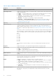
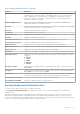
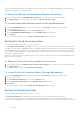
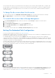
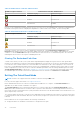
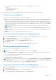
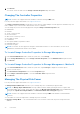
Table Of Contents
- Dell EMC Server Administrator Storage Management 9.5
- Contents
- Overview
- Getting Started
- Understanding RAID concepts
- RAID
- Organizing Data Storage For Availability And Performance
- Choosing RAID Levels And Concatenation
- Concatenation
- RAID level 0 - striping
- RAID level 1 - mirroring
- RAID level 5 -striping with distributed parity
- RAID level 6 - striping with additional distributed parity
- RAID level 50 - striping over RAID 5 sets
- RAID level 60 - striping over RAID 6 sets
- RAID level 10 - striped-mirrors
- RAID Level 1- Concatenated Mirror
- Comparing RAID Level And Concatenation Performance
- No-RAID
- Quick Access To Storage Status And Tasks
- PCI Express Solid-State Device Support
- PCIe SSD
- PCIe SSD Features
- PCIe SSD Subsystem Properties
- PCIe Extender Cards
- Physical Device Properties
- Physical Device Tasks
- PCIe SSD In Slot Card Tasks
- PCIe SSD In Slot Card Properties
- PCIe SSD In Slot Card Tasks
- Exporting The Log For A PCIe SSD In Slot Card
- Performing A Cryptographic Erase On An NVMe PCIe SSD In Slot Card
- PCIe SSD Subsystem Health
- Storage Information And Global Tasks
- Controllers
- Controller
- RAID Controller Technology - SATA And SAS
- RAID Controller Features
- Controller — Supported RAID Levels
- Controller — Supported Stripe Sizes
- RAID Controller Read, Write, and Disk Cache Policy
- Background Initialization On PERC Controllers
- Non-RAID Controller Description
- Firmware Or Driver Versions
- Controller Health
- Controllers Properties And Tasks
- Controller Tasks
- Creating A Virtual Disk
- Enabling The Controller Alarm
- Disabling The Controller Alarm
- Turning Off The Controller Alarm
- Testing The Controller Alarm
- Setting The Rebuild Rate
- Resetting The Controller Configuration
- Exporting The Controller Log File
- Foreign Configuration Operations
- Importing Foreign Configurations
- Importing Or Recovering Foreign Configurations
- Clearing Foreign Configuration
- Physical Disks In Foreign Virtual Disks
- Setting Background Initialization Rate
- Setting The Check Consistency Rate
- Setting The Reconstruct Rate
- Setting The Redundant Path Configuration
- Setting The Patrol Read Mode
- Starting And Stopping Patrol Read
- Changing The Controller Properties
- Managing The Physical Disk Power
- Properties In Manage Physical Disk Power Option
- Physical Disk Power On Unconfigured Drives And Hot Spares
- Managing Physical Disk Power Using The Customized Power Savings Mode
- Managing Physical Disk Power Using The QoS Option
- Managing The Time Interval For The QoS Option
- To Locate Manage Physical Disk Power In Storage Management
- Managing The Preserved Cache
- Encryption Key
- Converting To Non-RAID Disks
- Converting To RAID Capable Disks
- Changing The Controller Mode
- Auto Configure RAID0 Operation
- System Configuration Lock Down Mode
- Global Tasks Supported When System Configuration Lock Down Mode Is On
- Controller Tasks Supported When System Configuration Lock Down Mode Is On
- Controller Reports Supported When System Configuration Lock Down Mode Is On
- Physical Disk Tasks Supported When System Configuration Lock Down Mode Is On
- Virtual Disk Tasks Supported When System Configuration Lock Down Mode Is On
- Viewing Available Reports
- Support For PERC 9, PERC 10, and PERC 11 Hardware Controllers
- Support for BOSS RAID Controllers
- Enclosures And Backplanes
- Backplanes
- Enclosures
- MX5016s
- Enclosure Physical Disks
- Enclosure Fans
- Fan Properties
- Enclosure Power Supplies
- Power Supply Properties
- Enclosure Temperature Probes
- Enclosure Management Modules
- Enclosure And Backplane Health
- Enclosure And Backplane Properties And Tasks
- Enclosure And Backplane Properties And Tasks
- Enclosure Management
- Identifying An Open Connector On The Enclosure
- Enclosure Components
- Connectors
- Tape Drive
- RAID Controller Batteries
- Physical Disks Or Physical Devices
- Guidelines To Replace A Physical Disk Or Physical Device
- Adding A New Disk To The System
- Replacing A Physical Disk Receiving SMART Alerts
- Other Disk Procedures
- Physical Disk Or Physical Device Properties
- Physical Disk Or Physical Device Tasks
- Physical Disk Tasks
- Blinking And Unblinking A Physical Disk
- Removing Dead Segments
- Preparing To Remove
- Rebuilding Data
- Canceling A Rebuild
- Assigning And Unassigning Global Hot Spare
- Setting The Physical Disk Online Or Offline
- Performing A Clear Physical Disk And Cancel Clear
- Enabling Revertible Hot Spare
- Performing Cryptographic Erase
- Exporting The Log For PERC NVMe Drives
- Convert To RAID Capable Disk
- Convert To Non-RAID Disk
- Virtual Disks
- Considerations Before Creating Virtual Disks
- Virtual Disk Considerations For Controllers
- Virtual Disk Considerations For PERC S100, S110, S130, And S300 Controllers
- Virtual Disk Considerations On Systems Running Linux
- Number Of Physical Disks Per Virtual Disk
- Number Of Virtual Disks Per Controller
- Calculation For Maximum Virtual Disk Size
- Channel-Redundant Virtual Disks
- Creating Virtual Disks
- Reconfiguring Or Migrating Virtual Disks
- Starting And Target RAID Levels For Virtual Disk Reconfiguration And Capacity Expansion
- Maintaining The Integrity Of Redundant Virtual Disks
- Rebuilding Redundant Information
- Managing Virtual Disk Bad Block Management
- Recommendations For Clearing Bad Blocks
- Virtual Disk Properties And Tasks
- Virtual Disk — Available Tasks
- Reconfiguring A Virtual Disk
- Format, Initialize, Slow, And Fast Initialize
- Canceling Background Initialization
- Restoring Dead Segments
- Deleting Data On the Virtual Disk
- Performing A Check Consistency
- Cancelling A Check Consistency
- Pausing A Check Consistency
- Resuming A Check Consistency
- Blinking And Unblinking A Virtual Disk
- Renaming A Virtual Disk
- Canceling A Rebuild
- Changing The Virtual Disk Policy
- Replacing A Member Disk
- Clearing Virtual Disk Bad Blocks
- Encrypting A Virtual Disk
- Create Virtual Disk Express Wizard
- Create Virtual Disk Express Wizard Step 2
- Create Virtual Disk Advanced Wizard
- Create Virtual Disk Advanced Wizard Step 2
- Create Virtual Disk Advanced Wizard Step 3
- Span Edit
- Virtual Disk Task - Reconfigure Step 1 of 3
- Virtual Disk Task - Reconfigure Step 2 of 3
- To Reconfigure A Virtual Disk Expand Virtual Disk Capacity - Step 2 of 3
- Virtual Disk Task - Reconfigure Step 3 of 3
- Slow And Fast Initialize
- Formatting Or Initializing A Disk
- Deleting A Virtual Disk
- Renaming A Virtual Disk
- Changing The Policy Of A Virtual Disk
- Split Mirror
- Unmirror
- Assigning And Unassigning Dedicated Hot Spare
- Virtual Disk Task - Replace Member Disk Step 1 of 2
- Virtual Disk Task - Replace Member Disk Step 2 of 2
- Considerations Before Creating Virtual Disks
- Moving Physical And Virtual Disks From One System To Another
- Protecting Your Virtual Disk With A Hot Spare
- Troubleshooting
- Common Troubleshooting Procedures
- Virtual Disk Troubleshooting
- A Rebuild Does Not Work
- A Rebuild Completes With Errors
- Cannot Create A Virtual Disk
- A Virtual Disk Of Minimum Size Is Not Visible To Windows Disk Management
- Virtual Disk Errors On Systems Running Linux
- Problems Associated With Using The Same Physical Disks For Both Redundant And Non-Redundant Virtual Disks
- Specific Problem Situations And Solutions
- Physical Disk Is Offline Or Displays An Error Status
- Receive A Bad Block Alert With Replacement, Sense, Or Medium Error
- Alerts 2146 Through 2150 Received During A Rebuild Or While A Virtual Disk Is Degraded
- Alerts 2146 Through 2150 Received While Performing IO, Consistency Check, Format, Or Other Operation
- Read And Write Operations Experience Problems
- A Task Menu Option Is Not Displayed
- A Corrupt Disk Or Drive Message Suggests Running Autocheck During A Reboot
- Erroneous Status And Error Messages After A Windows Hibernation
- Storage Management May Delay Before Updating Temperature Probe Status
- Storage Management May Delay Displaying Storage Devices After Reboot
- You Are Unable To Log Into A Remote System
- Cannot Connect To Remote System Running Microsoft Windows Server 2003
- Reconfiguring A Virtual Disk Displays Error In Mozilla Browser
- Physical Disks Are Displayed Under The Connector Object Instead Of The Enclosure Object
- PCIe SSD Troubleshooting
- Frequently Asked Questions
- Why Is A Rebuild Not Working
- How To Avoid Removing The Wrong Disk
- How Can I Safely Remove Or Replace A Physical Disk
- How Do I Recover From Removing The Wrong Physical Disk
- How Do I Identify The Firmware Version That Is Installed
- Which Controllers Do I Have
- How Do I Turn Off An Alarm
- Which RAID Level Is Best For Me
- Supported Features
- Supported Features On PERC Hardware Controllers
- Controller Tasks Supported On PERC Hardware Controllers
- Battery Tasks Supported On PERC Hardware Controllers
- Physical Disk Tasks Supported By PERC Hardware Controllers
- Virtual Disk Tasks Supported By PERC Hardware Controllers
- Virtual Disk Specifications For PERC Hardware Controllers
- RAID Levels Supported By PERC Hardware Controllers
- Read, Write, Cache And Disk Cache Policy Supported By PERC Hardware Controllers
- Supported Features On PERC H200 Controllers
- Controller Tasks Supported On H200 Controllers
- Battery Tasks Supported On H200 Controllers
- Connector Tasks Supported On H200 Controllers
- Physical Disk Tasks Supported On H200 Controllers
- Virtual Disk Tasks Supported On H200 Controllers
- RAID Levels Supported By H200 Controllers
- Virtual Disk Specifications For PERC H200 Controllers
- Read, Write, And Cache Policy Supported By H200 Controllers
- Enclosure Support On H200 Controllers
- Supported Features On The PERC Software RAID Controllers
- Controller Tasks Supported On The PERC Software RAID Controllers
- Physical Disk Tasks Supported By The PERC Software RAID Controllers
- Virtual Disk Tasks Supported By The PERC Software Controllers
- Virtual Disk Specifications For PERC Software RAID Controllers
- RAID Levels Supported By The PERC Software RAID Controllers
- Read Write Cache And Disk Cache Policy Supported By The PERC Software RAID Controllers
- Enclosure Support On The PERC Software RAID Controllers
- Supported Features On The Non-RAID Controllers
- Controller Tasks Supported On The Non-RAID Controllers
- Battery Tasks Supported By Non-RAID Controllers
- Connector Tasks Supported On The Non-RAID Controllers
- Physical Disk Tasks Supported On The Non-RAID Controllers
- Virtual Disk Tasks Supported By The Non-RAID Controllers
- Enclosure Support On The Non-RAID Controllers
- Enclosure And Backplane Features
- Enclosure And Backplane Tasks
- Maximum Supported Configuration For SAS Controllers
- Supported Features On PERC Hardware Controllers
- Determining The Health Status For Storage Components
- Health Status Rollup - Battery Is Charging Or Dead
- Health Status Rollup - Physical Disks In A Virtual Disk Are Failed Or Removed
- Health Status Rollup - Physical Disks In A Virtual Disk Are Unsupported, Partially, Or Permanently Degraded
- Health Status Rollup - All Physical Disks In A Virtual Disk Are In Foreign State
- Health Status Rollup - Some Physical Disks In A Virtual Disk Are In Foreign State
- Health Status Rollup - Virtual Disk Is Degraded, Physical Disks Are Failed Or Rebuilding
- Health Status Rollup - Virtual Disk Is Failed
- Health Status Rollup - Unsupported Firmware Version
- Health Status Rollup - Enclosure Power Supply Failed Or Power Connection Removed
- Health Status Rollup - One Enclosure Fan Is Failed
- Health Status Rollup - One Enclosure EMM Is Failed
- Health Status Rollup - One Enclosure Temperature Probe Is Failed
- Health Status Rollup - Lost Both Power Connections To The Enclosure
- Health Status Rollup - One Or More Physical Disks Are Failed
- Health Status Rollup - Physical Disk Is Rebuilding
- Identifying the series of your Dell EMC PowerEdge servers

Table 14. Path between Controller and Enclosure 1
Health of Logical Connector Path between Controller and Enclosure 1
Connector 0 (C0) Connector 1 (C1)
Available Available
Available Disconnected
Disconnected Available
However, if the communication channel between any two enclosures is lost, the redundant path configuration is degraded and
the health of the logical connector is displayed as degraded. For a brief outline of this scenario, see the following table.
Table 15. Path between Enclosure
n
and Enclosure
n
+1
Health of Logical Connector Path between Enclosure
n
and Enclosure
n
+1
Connector 0 (C0) Connector 1 (C1)
Available Available
Available Disconnected
Disconnected Available
In the above scenario, the enclosure status is displayed in warning mode. Clicking Information/Configuration in the
Enclosures page displays all enclosure components (EMMs, Fans, Physical Disks, Power Supplies, and Temperature) in normal
condition. To view the Path Failure message to indicate that the enclosure has lost a communication path to the controller,
indicating that the enclosure is no longer in redundant path mode.
Clearing The Redundant Path View
Consider a case where you reboot your system and Storage Management, displays the logical connector with a path failure
message. It is possible that you may have intentionally unplugged the second connector. In this case, the path failure message
is not relevant. There could be a fault in the connected cable or the cable may not be connected properly to the controller. In
both cases, Storage Management displays that the system was in redundant path configuration before reboot and is no longer
in this configuration. If you are sure you, do not want the redundant path mode, clear the existing redundant path view using
Clear Redundant Path View provided in the Changing The Controller Properties controller task. Selecting this option clears
the redundant path view and the connectors are represented on the user interface as Connector 0 and Connector 1.
Setting The Patrol Read Mode
NOTE: This task is not supported on PERC hardware controllers running in HBA mode.
Does my controller support this feature? See Supported Features.
Patrol read identifies disk errors in order to avoid disk failures and data loss or corruption. The Set Patrol Read task is
applicable only for disks used as virtual disks or hot spares.
The Set Patrol Read task runs in the background and corrects, when possible. When the Set Patrol Read mode is set to
Auto, patrol read is initiated when the controller is idle for a period of time and when no other background tasks are active. In
this scenario, the patrol read enhances the system performance as disk errors can be identified and corrected when there is not
input/output activity on the disk.
The controller adjusts the amount of system resources dedicated for patrol read based on the amount of controller activity that
is competing with the Patrol Read task. When the controller activity is high, fewer system resources are dedicated to the patrol
read task.
Patrol Read does not run on a physical disk in the following circumstances:
● The physical disk is not included in a virtual disk or is assigned as a hot spare.
68
Controllers