Dell OpenManage Server Administrator Version 8.
Notes, cautions, and warnings NOTE: A NOTE indicates important information that helps you make better use of your product. CAUTION: A CAUTION indicates either potential damage to hardware or loss of data and tells you how to avoid the problem. WARNING: A WARNING indicates a potential for property damage, personal injury, or death. © 2016 Dell Inc. All rights reserved. This product is protected by U.S. and international copyright and intellectual property laws.
Contents 1 Introduction.....................................................................................................................6 Server Administrator.......................................................................................................................................................... 6 Documenting CIM Classes and Their Properties.................................................................................................................6 Base Classes......................
CIM_Keyboard................................................................................................................................................................. 37 CIM_PowerSupply........................................................................................................................................................... 37 CIM_Controller...................................................................................................................................................
CIM_Dependency......................................................................................................... 78 DELL_FanSensor............................................................................................................................................................. 78 CIM_PackageTempSensor...............................................................................................................................................79 CIM_PackageVoltSensor........................
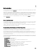
1 Introduction This reference guide documents the Dell OpenManage Server Administrator Common Information Model (CIM) provider contained in the Management Object File (MOF) dccim32.mof. CIM provides a conceptual model for describing manageable objects in a systems management environment. CIM is a modeling tool rather than a programming language. CIM provides the structure for organizing objects into a model of a managed environment.
• DELL_EsmLog: RecordNumber • DELL_PostLog: RecordNumber • DELL_BIOSExtensions: systemBIOSCharacteristics • DELL_BIOSSettings: DisplayName • CIM_ServiceAccessPoint: SystemCreationClassName, SystemName, CreationClassName, Name Base Classes The classes listed in the Server Administrator CIM provider class hierarchy do not have a parent property. These base classes do not derive from another class.
Dell-Defined Classes Server Administrator has extended some CIM classes and has created new classes to assist in managing systems and their components. In this document, the illustrations of the classes created and populated by Dell are represented by an orange circle icon. Common Properties of Classes Many classes have properties such as Caption, Description, and CreationClassName.
Property Description Data Type Name Defines the label by which the object is known. When subclassed, the Name property can be overridden to be a Key property. string Status Provides a string indicating the status of the component. Status values include: string Operational Status Values: • • • OK indicates that the object is functioning normally. Degraded means that the item is functioning, but not optimally. Stressed indicates that the element is functioning, but needs attention.
Other Documents You May Need Besides this Dell OpenManage Server Administrator CIM Reference Guide, you can find the following documents on the Dell Support website at dell.com/support/manuals: • Dell OpenManage Server Administrator User’s Guide documents the features, installation, and uninstallation of Server Administrator. • Dell OpenManage Server Administrator Installation Guide contains instructions to help you install Dell OpenManage Server Administrator.
2 CIM_Physical Element CIM_PhysicalElement is a CIM-defined class. The CIM_PhysicalElement class contains the subclasses shown in Figure CIM_PhysicalElement Class Structure CIM_PhysicalElement Subclasses of the CIM_PhysicalElement class listed in Table below define any component of a system that has a distinct physical identity. Physical elements are tangible managed system elements (usually actual hardware items) that have a physical manifestation of some sort.
SerialNumber A manufacturer-allocated number used to identify the physical element. string Tag Uniquely identifies the physical string element and serves as the element’s key. The Tag property can contain information such as asset tag or serial number data. The key for a physical element is placed very high in the object hierarchy in order to identify the hardware/entity independently, regardless of the physical placement in or on cabinets, adapters, and so on.
different element for the original element, as in a field replaceable unit (FRU). For example, some computer systems allow the microprocessor to be upgraded to one of a higher clock rating. In this case, the microprocessor is said to be replaceable. CIM_PhysicalFrame The CIM_PhysicalFrame class described in Table properties contains other frame enclosures such as racks and chassis. Properties like VisibleAlarm or AudibleAlarm, and data related to security breaches are also members of this class. Table 5.
Table 6. CIM_Chassis Parent Properties Class Name: CIM_Chassis Parent Class:CIM_PhysicalFrame Property Description Data Type ChassisTypes Values for the ChassisTypes property are: uint16 1. 2. 3. 4. 5. 6. 7. 8. 9. 10. 11. 12. 13. 14. 15. 16.
Class Name: DELL_Chassis Parent Class: CIM_Chassis Property Description Data Type 1 - Other 2 - Unknown 3 - Workstation 4 Server 5 - Desktop 6 - Portable 7 - Net PC SystemID Indicates the system identifier code. uint16 LogFormat Defines whether the event log data is unicode formatted or binary (raw).
Class Name: DELL_Chassis Parent Class: CIM_Chassis Property Description Data Type MemoryRedStatus Indicates the global status of memory redundancy. string ChassisExpressServiceCode Indicates the chassis express service code. string ChassisNodeID Chassis Node ID string CIM_PhysicalComponent The CIM_PhysicalComponent class listed in Table below represents any low-level or basic component within a package.
4 — ZIP 5 — SOJ 6 — Proprietary 7 — SIMM 8 — DIMM 9 — TSOP 10 — PGA 11 — RIMM 12 — SODIMM 13 — SRIMM 14 — SMD 15 — SSMP 16 — QFP 17 — TQFP 18 — SOIC 19 — LCC 20 — PLCC 21 — BGA 22 — FPBGA 23 — LGA 24 — FB-DIMM CIM_PhysicalMemory The CIM_PhysicalMemory class listed in PhysicalMemoryProperties is a subclass of CIM_Chip, representing low-level memory devices, such as SIMMs, DIMMs, and so on. Table 10.
MemoryType Indicates the type of physical memory. Values for the MemoryType property are: 0 - Unknown uint16 1 - Other 2 - DRAM 3 - Synchronous DRAM 4 - Cache DRAM 5 - EDO 6 - EDRAM 7 - VRAM 8 - SRAM 9 - RAM 10 - ROM 11 — Flash 12 - EEPROM 13 - FEPROM 14 - EPROM 15 - CDRAM 16 - 3DRAM 17 - SDRAM 18 - SGRAM 19 - RDRAM 20 - DDR 21 - DDR2 22 - DDR2 FB-DIMM 24 - DDR3 25 - FBD2 26 - DDR4 TotalWidth 18 Indicates the total width, in bits, of the physical memory, including check or error correction bits.
DataWidth Indicates the data width, in uint16 bits, of the physical memory. A data width of 0 and a total width of 8 would indicate that the memory is solely used to provide error correction bits. Speed Indicates the speed of the physical memory, in nanoseconds. uint32 Rank The Rank values of DIMM are: unit32 0 - Unknown 1 - Single 2 - Dual 4 - Quad 8 - Octal 16 - Hexa SpeedAsString Indicates the accurate speed of the physical memory, in string format (with units).
CIM_PhysicalConnector The CIM_PhysicalConnector class listed in Physical Connector Properties includes physical elements such as plugs, jacks, or buses that connect physical elements. Any object that can be used to connect and transmit signals or power between two or more physical elements is a member of this class. For example, slots and D-shell connectors are types of physical connectors. See Connector Type Values for a list of valid connector type values. Table 11.
10 - SCSI SCA-II (80 pins) 40 - Fiber MIC 70 - Mini-Centronics Type-26 100 - Sbus IEEE 1396-1993 64bit 11 - Fibre Channel (DB-9 Copper) 41 - unused 71 - Bus mouse 101 - unused 12 - Fibre Channel (Fiber Optical) 42 - unused 72 - ADB 102 - GIO 13 - Fibre Channel SCAII (40 pins) 43 - PCI 73 - AGP 103 - XIO 14 - Fibre Channel SCAII (20 pins) 44 - ISA 74 - VME bus 104 - HIO 15 - Fibre Channel BNC 45 - unused 75 - VME64 105 - NGIO 16 - ATA 3-1/2 inch (40 pins) 46 - VESA 76 - Proprietary
ConnectorType See Connector Type Values uint16 SupportsHotPlug Indicates whether the slot supports hot-plug adapter cards. Boolean MaxDataWidth Indicates the maximum bus uint16 width in bits of adapter cards that can be inserted into this slot. Values for the MaxDataWidth property are as follows: 0 - Unknown 1 - Other 8 - bits 16 - bits 32 - bits 64 - bits 128 - bits SystemSlotType Indicates the type of system slot.
17 - AGP 4X 18 - PCI-X 19 - AGP 8X 160 - PC-98/C20 161 - PC-98/C24 162 - PC-98/E 163 - PC-98/Local bus 164 - PC-98/Card 165 - PCI Express 166 - PCI Express x1 167 - PCI Express x2 168 - PCI Express x4 169 - PCI Express x8 170 - PCI Express x16 171 - PCI Express Gen 2 172 - PCI Express Gen 2 x1 173 - PCI Express Gen 2 x2 174 - PCI Express Gen 2 x4 175 - PCI Express Gen 2 x8 176 - PCI Express Gen 2 x16 23
3 CIM_LogicalElement CIM_LogicalElement is a CIM-defined class containing the subclasses described in below Figure.
CIM_LogicalElement Table properties list the following characteristics for members of the CIM_LogicalElement class: • Represent abstractions used to manage and coordinate aspects of a physical environment such as files, processes, systems, system capabilities, and network components in the form of logical devices • Represent devices, where devices are abstractions of hardware entities that may or may not be realized in physical hardware Table 14.
plays in the IT environment. For example, for an instance of a network system, the Roles property might contain the string "storage system." CIM_ComputerSystem The CIM_ComputerSystem class described in Table below contains some or all of the following CIM_ManagedSystemElements: file system, operating system, processor, and memory (volatile and/or nonvolatile storage). For properties, see CIM_System Properties. Table 16.
Table 18. CIM_Logical Device Properties Class Name: CIM_LogicalDevice Parent Class: CIM_LogicalElement Property Description Data Type SystemCreationClassName See Common Properties of Classes string SystemName Indicates the scoping system’s name. string CreationClassName See Common Properties of Classes string DeviceID Identifies an address or other identifying information to uniquely name the logical device.
FRUSerialNumberName Indicates the FRU serial number. string FRURevisionName Indicates the FRU revision number. string CIM_Sensor The CIM_Sensor class described in Table below contains hardware devices capable of measuring the characteristics of some physical property, for example, the temperature or voltage characteristics of a computer system Table 20.
SensorType property is set to Other. PossibleStates Enumerates the string outputs of the sensor. For example, a NumericSensor can report states based on threshold readings. string CurrentState Indicates the current state of string the sensor. This value is always one of the Possible States. PollingInterval Indicates the polling interval, in nanoseconds, that the sensor hardware or instrumentation uses to determine the current state of the sensor.
Figure: Ranges for Threshold Values Table 22.
LowerThresholdNonCritical See Common Properties of Classes sint32 UpperThresholdNonCritical See Common Properties of Classes sint32 LowerThresholdCritical See Common Properties of Classes sint32 UpperThresholdCritical See Common Properties of Classes sint32 SupportedThresholds An array representing the thresholds supported by this sensor.
Table 23.
CIM_VoltageSensor The CIM_VoltageSensor class described in Table below contains sensors that measure voltage and return a value in volts. Table 25.
LowerThresholdNonCritical See Common Properties of Classes sint32 UpperThresholdNonCritical See Common Properties of Classes sint32 CIM_WatchDog The CIM_WatchDog class described in Table below represents a timer that is implemented in system hardware. The watchdog feature allows the hardware to monitor the state of the operating system, BIOS, or a software component installed on the system.
The CIM_CoolingDevice class described in CIM_CoolingDevice contains a set of devices that work to keep the ambient internal temperature of the system at a safe value. Table 28. CIM_CoolingDevice Properties Class Name: CIM_CoolingDevice Parent Class: CIM_LogicalDevice Property Description Data Type ActiveCooling Specifies whether the device provides active (as opposed to passive) cooling.
Table 30. CIM_UserDevice Properties Class Name: CIM_UserDevice Parent Class: CIM_LogicalDevice Property Description Data Type IsLocked Indicates if the device is locked, preventing user input or output. Boolean CIM_PointingDevice The CIM_PointingDevice class described in Table below includes those devices used to point to regions of a display. Examples of such devices are a mouse or a trackball. Table 31.
1 — Not applicable 2 — Right-handed operation 3 — Left-handed operation CIM_Keyboard The CIM_Keyboard class described in Table below includes devices that allow users to enter data. Table 32. CIM_Keyboard Properties Class Name: CIM_Keyboard Parent Class: CIM_UserDevice Property Description Data Type NumberOfFunctionKeys Indicates the number of function keys on the keyboard. uint16 Layout A free-form string indicating the format and layout of the keyboard.
Table 33. CIM_PowerSupply Properties Class Name: CIM_PowerSupply Parent Class: CIM_LogicalDevice Property Description Data Type IsSwitchingSupply Indicates that the power supply is a switching power supply and not a linear power supply. Boolean Range1InputVoltageLow Indicates the low voltage in millivolts of input voltage range 1 for this power supply. A value of 0 denotes unknown.
Table 34. CIM_Controller Properties Class Name: CIM_Controller Parent Class: CIM_LogicalDevice Property Description Data Type ProtocolSupported The protocol used by the controller to access controlled devices. Values for the ProtocolSupported property are: 1 — Other uint16 2 — Unknown 3 — PCI 4 — Parallel protocol CIM_ParallelController The CIM_ParallelController class described in below contains a set of objects that control parallel devices.
CIM_SerialController The CIM_SerialController class described in Table below contains controllers that transfer data one bit at a time to the devices they control, for example, a serial port controlling a modem. Table 36. CIM_SerialController Properties Class Name: CIM_SerialController Parent Class: CIM_Controller Property Description Data Type MaxBaudRate Indicates the maximum baud rate in bits per second supported by the serial controller.
Table 37. CIM_PCIController Properties Class Name: CIM_PCIController Parent Class: CIM_Controller Property Description Data Type CommandRegister The current contents of the register that provide basic control over the device’s ability to respond to, and/or perform PCI accesses. The data in the capabilities array is gathered from the PCI status register and the PCI capabilities list as defined in the PCI specification.
Table 38. CIM_PCIDevice Properties Class Name: CIM_PCIDevice Parent Class: CIM_PCIController Property Description Data Type BaseAddress Identifies an array of up to six double-word base memory addresses. uint32 SubsystemID Identifies a subsystem identifier code. uint16 SubsystemVendorID Identifies a subsystem vendor ID. ID uint16 information is reported from a PCI device via protocol-specific requests.
BaseAddress Identifies an array of double-word base memory addresses. uint32 CIM_Processor The CIM_Processor class described in Table below contains devices that interpret and execute commands, for example, the Intel Xeon microprocessor. Table 40. CIM_Processor Properties Class Name: CIM_Processor Parent Class: CIM_LogicalDevice Property Description Data Type Role A string describing the role of the microprocessor, for example, central microprocessor or math processor.
23 - Socket AM2 24 - Socket F (1207) 25— Socket LGA1366 MaxClockSpeed Indicates the maximum speed (in MHz) of uint32 this microprocessor. Core count Indicates the number of core processors detected. uint16 CoreEnabledCount Indicates the number of core processors enabled. uint16 CurrentClockSpeed Indicates the current speed (in MHz) of this microprocessor. uint32 DataWidth Indicates the processor data width in bits. uint16 AddressWidth Indicates the processor address width in bits.
CPUStatus Indicates the current status of the microprocessor. For example, it may be disabled by the user through the BIOS or disabled due to a POST error. Values for the CPUStatus property are as follows: uint16 0 - Unknown 1 - Microprocessor enabled 2 - Microprocessor disabled by user through BIOS setup 3 - Microprocessor disabled by BIOS (POST error) 4 - Microprocessor is idle 5 - Other Family Refers to the processor family type.
24 — AMD Duron processor 25 — K5 family 26 - K6 family 27 - K6 -2 28 - K6-3 29 - AMD Athlon processor family 30 - AMD29000 family 31 - K6-2+ 32 - Power PC family 33 - Power PC 601 34 - Power PC 603 35 - Power PC 603+ 36 - Power PC 604 37 - Power PC 620 38- Power PC X704 39- Power PC 750 40 - Intel Core Duo processor 41 - Intel Core Duo mobile processor 42 - Intel Core Solo mobile processor 43 - Intel Atom processor 48 - Alpha family 49 - Alpha 21064 50 - Alpha 21066 51 - Alpha 21164 52 - Alpha 21164 53 - Al
67 - MIPSR4400 68 - MIPS R4600 69 - MIPS R10000 80 - SPARC family 81 - SuperSPARC 82 - microSPARC II 83 - microSPARC IIep 84 - UltraSPARC 85 - UltraSPARC II 86 - UltraSPARC IIi 87 - UltraSPARC III 88 - UltraSPARC IIIi 96 - 68040 97 - 68xxx family 98 - 68000 99 - 68010 100 - 68020 101 - 68030 112 - Hobbit family 120 - Crusoe 5000 family 121 - Crusoe 3000 family 122 - Efficeon 8000 family 128 - Weitek 130 - Itanium processor 131 - AMD Athlon 64 processor family 132 - AMD Opteron processor family 133 - AMD Sem
138 - Quad-Core AMD Opteron processor family 139 - Third-Generation AMD Opteron processor family 140 - AMD Phenom FX Quad-Core processor family 141 - AMD Phenom X4 Quad-Core processor family 142 - AMD Phenom X2 Dual-Core processor family 143 - AMD Athlon X2 Dual-Core processor family 144 - PA-RISC family 145 - PA-RISC 8500 146 - PA-RISC 8000 147 - PA-RISC 7300LC 148 - PA-RISC 7200 149 - PA-RISC 7100LC 150 - PA-RISC 7100 160 - V30 family 161 - Quad-Core Intel Xeon processor 3200 Series 162 - Dual-Core Intel
172- Dual-Core Intel Xeon processor 7200 Series 173 - Quad-Core Intel Xeon processor 7300 Series 174- Quad-Core Intel Xeon processor 7400 Series 175- Multi-Core Intel Xeon processor 7400 Series 176 - Pentium III Xeon 177 - Pentium III Processor with Intel SpeedStep 178- Technology 179 - Pentium 4 180 - Intel Xeon 181- AS400 family 182 - Intel Xeon Processor MP 183 - AMD Athlon XP family 184 - AMD Athlon MP family 185 - Intel Itanium 2 186- Intel Pentium M processor 187 - Intel Celeron D processor 188 - Inte
202- ESA/390 G5 203- ESA/390 G6 204 - z/Architecture base 206 - CEh 206 Intel Core i3 processor 214 - Multi-Core Intel Xeon processor 215 - Dual-Core Intel Xeon processor 3xxx Series 216 - Quad-Core Intel Xeon processor 3xxx Series 217 - D9h 217 VIA Nano processor family 218 - Dual-Core Intel Xeon processor 5xxx Series 219 - Quad-Core Intel Xeon processor 5xxx Series 221 - Dual-Core Intel Xeon processor 7xxx Series 222- Dual-Core Intel Xeon processor 7xxx Series 223 Multi-Core Intel Xeon processor 7xxx Seri
280 - ARM 281 - StrongARM 300 - 6x86 301 - MediaGX 302 - MII 320 - WinChip 350- DSP 500 - Video processor CIM_StorageExtent The CIM_StorageExtent identified in Table below contains devices that manage data storage, for example, hard drives or microprocessor memory. Table 41.
CIM_CacheMemory The CIM_CacheMemory class described in CacheMemoryProperties describes the capabilities and management of cache memory. Cache memory allows a microprocessor to access data and instructions faster than normal system memory Table 43. CIM_CacheMemory Properties Class Name: CIM_CacheMemory Parent Class: CIM_Memory Property Description Level Defines if this is the primary, secondary, or uint16 tertiary cache.
1- Other 2- Unknown 3- Instruction 4- Data 5- Unified LineSize Indicates the size, in bytes, of a single cache bucket or line. uint32 ReadPolicy Defines the policy used by the cache for handling read requests.
CIM_BIOSElement The CIM_BIOSElement class listed in BIOSElement Properties describes the BIOS for the system. The BIOS controls the following: • Communications between the microprocessor and peripheral devices, such as the keyboard and the video adapter. • Miscellaneous functions, such as system messages. Table 45. CIM_BIOSElement Properties Class Name: CIM_BIOSElement Parent Class: CIM_SoftwareElement Property Description Data Type Version Provides the product version information.
ProductName Identifies the commonly used product name. string Vendor Identifies the name of the product’s supplier. Corresponds to the vendor property in the product object in the DMTF solution exchange standard. string Version Identifies the product version information. string Corresponds to the version property in the product object in the DMTF solution exchange standard. Name Defines the label by which the object is known to the users.
The CIM_SystemResource class described in Table below provides access to system resources from an operating system. System resources consist of interrupt requests (IRQs) and direct memory access (DMA) capabilities. Table 48. CIM_SystemResource Properties Class Name: CIM_SystemResource Parent Class: CIM_LogicalElement CIM_IRQ The CIM_IRQ class described in Properties Table below , contains IRQ information. An IRQ is a signal that data is about to be sent to or received by a peripheral device.
TriggerType Indicates if edge (value=4) or level triggered (value=3) interrupts occur. 1- Other uint16 2- Unknown 3- Level 4- Edge Shareable Indicates if the IRQ can be shared. A value Boolean of TRUE indicates that the IRQ can be shared. Hardware Indicates if the interrupt is hardware- or Boolean software-based. (A value of TRUE indicates that the interrupt is hardware based.
MappedResource Indicates the type of memory mapped I/O. MappedResource defines if memory or I/O is mapped, and for I/O, if the mapping is to a memory or a port space. Memory mapped I/O values are as follows: 1- Other uint16 2- Mapped memory 3 - I/O mapped to memory space 4- I/O mapped to port space CIM_DMA The CIM_DMA class described in DMA Properties contains DMA information. A DMA channel allows certain types of data transfer between RAM and a device to bypass the microprocessor. Table 51.
CIM_RedundancyGroup The CIM_RedundancyGroup class described in Table properties below is a set of components that provide more instances of a critical component than are required for the system’s operation. The extra components are used in case of critical component failure. For example, multiple power supplies allow a working power supply to take over when another power supply has failed. Table 52.
The CIM_ExtraCapacityGroup class described in below properties Table applies to systems that have more capability and components than are required for normal operation, for example, systems that have extra fans or power supplies. Table 53. CIM_ExtraCapacityGroup Properties Class Name: CIM_ExtraCapacityGroup Parent Class: CIM_RedundancyGroup Property Description MinNumberNeeded Specifies the smallest number of elements uint32 that must be operational in order to have redundancy.
CIM_EnabledLogicalElement The CIM_EnabledLogicalElement class described in Table below extends the CIM_LogicalElement class to abstract the concept of an element that is enabled or disabled, such as a LogicalDevice or ServiceAccessPoint. Table 56. CIM_EnabledLogicalElement Properties Class Name: CIM_EnabledLogicalElementGroup Parent Class: CIM_LogicalElementGroup CIM_ServiceAccessPoint The CIM_ServiceAccessPoint class described in Table below represents the ability to utilize or invoke a service.
Table 58. CIM_RemoteServiceAccessPoint Properties Class Name: CIM_RemoteServiceAccessPointGr oup Parent Class: CIM_ServiceAccessPointGroup Property Description Data Type AccessInfo Describes accessing or addressing of information for a remote connection. This can be a host name, network address, and other similar information. string InfoFormat Indicates an enumerated integer describing the format and interpretation of the AccessInfo property.
DELL_RemoteServiceAccessPort The DELL_RemoteServiceAccessPort class described in Table below is an extended class of the CIM_RemoteServiceAccessPoint class. The DELL_RemoteServiceAccessPort class provides information about Dell implementation-specific attributes Table 59. DELL_RemoteServiceAccessPort Properties Class Name: DELL_RemoteServiceAccessPort Parent Class: CIM_RemoteServiceAccessPoint Property Description Data Type PortName Displays the name of the service access port.
6- 1UQuarterWidth 7- 1UFullWidth 255- notApplicable 64
4 Dell-Defined Classes Dell-defined classes are defined and populated by Dell rather than by the Common Information Model (CIM). For information on how the logs are formatted, see DELL_Chassis Properties. The DELL_EsmLog class described in DELL_EsmLog Properties records failure threshold violations collected by Server Administrator’s embedded server management (ESM) capabilities. Table 60.
DELL_CMApplication NOTE: Dell-updateable components, such as BIOS and firmware, are considered applications. The DELL_CMApplication class described in DELL_CMApplication contains information related to the Dell change management applications. Table 62. DELL_CMApplication Class Name: DELL_CMApplication Parent Class: None Property Description Data Type componentType Defines the application type. string subComponentID Defines an application string.
vendorID Defines an ID for vendor supplying the device. string subVendorID Defines an ID for an additional vendor supplying the device. string deviceID Indicates the ID of the device. string subDeviceID Indicates the ID for additional device. string bus Indicates the PCI bus number. string device Indicates the PCI device number. string function Indicates the PCI function number.
Property Description Data Type local Indicates the locale of the system. string schemaVersion Indicates the inventory schema string implemented by the system. systemID Defines the system ID. string DELL_CMOS The DELL_CMOS class described in DELL_CMOS Properties contains information related to the Dell change management operating system. Table 66.
The DELL_CMProductInfo class described in DELL_CMProductInfo Properties contains information related to the Dell change management product. Table 67. DELL_CMProductInfo Properties Class Name: DELL_CMProductInfo Parent Class: None Property Description Data Type name Indicates the name of the product. string description Provides a short description of the product. string vendor Indicates the name of the product manufacturer. string version Indicates the current version number of the product.
Table 69. DELL_BIOSSettings Properties Class Name: DELL_BIOSSettings Parent Class: CIM_ManagedSystemElement Property Description Data Type DellInstanceID Defines the instance ID of this class. uint32 TrustedPlatformModule Enables or Disables the Trusted Platform Module (TPM).
Class Name: DELL_SDCardDevice Parent Class: CIM_LogicalDevice sdCardFreeSizeMB Indicates the available size of SD Media in MB. sdCardState Indicates the value of the SD Card. The values for this property are: uint32 0 - Present 1 and 2 - Reserved 3 - Offline Detected 4 - Failed Detectez 5 - Active 6 - Bootable 7 - Write Protected DELL_NetworkPort The Dell_Network Port class described in DELL_NetworkPort Properties represents the Dell-specific features of the network adapters. Table 71.
Bit 2, Value 0 - NIC is not iSOE capable. Bit 2, Value 1 - NIC is iSOE capable. Bit 3, Value 0 - NIC is not FCoE capable. Bit 3, Value 1 - NIC is FCoE capable. NIC TOE Capability Defines the TOE capability of the NIC. Values for the NIC TOE Capability property are: uint 32 0 - NIC/driver does not support querying for capability. 1 - NIC/driver supports querying for capability but query returned an error. 2 - NIC/driver supports querying for capability and querying indicates that it is capable.
NOTE: Boolean value is defined if RDMA is enabled (Boolean is RDMAEnable). NIC iSCSI Capability Defines the iSCSI capability of the NIC. Values for the NIC iSCSI Capability property are: uint 32 0 - NIC/driver does not support querying for capability. 1 - NIC/driver supports querying for capability but query returned an error. 2 - NIC/driver supports querying for capability and querying indicates that it is capable.
BusNumber Indicates the PCI bus number. uint 8 DeviceNumber Indicates the PCI device number. uint 8 FunctionNumber Indicates the PCI function number. uint 8 DriverVersion Indicates the NIC driver version. string IPAddresss Indicates the NIC IP address. string SubnetMask Indicates the NIC subnet mask. string DHCPServer Indicates the DHCP server. string DefaultGateway Indicates the default gateway. string CurrentMacAddress Indicates the NIC’s current MAC address.
Table 73.
DCIM_OEM_DataAccessModule The DCIM_OEM_DataAccessModule class is derived from the CIM_ManagedElement class. This class models hardware information in a proprietary format. Table 75. DCIM OEM DataAccessModule Class Name: DCIM_OEM_DataAccessModule Parent Class: CIM_ManagedElement Property Description Data Type InstanceID Identifies the instance. string GlobalStatus Represents the global health status of the system.
DCIM_RegisteredProfile The DCIM_RegisteredProfile class is derived from the CIM_RegisteredProfile class. This class advertises the capabilities of DCIM_OEM_DataAccessModule.
5 CIM_Dependency The CIM_Dependency class is an association used to establish dependency relationships between two managed system elements. The CIM_Dependency class described in the figure below does not have a parent class because it is a relationship or association between two elements.
CIM_PackageTempSensor The CIM_PackageTempSensor class described in CIM_PackageTempSensor Properties contains temperature sensors that are often installed in a package such as a chassis or a rack to assist in the monitoring of the package in general. This relationship is described by the CIM_PackageTempSensor association. Table 77.
CIM_PackageCurrentSensor The CIM_PackageCurrentSensor class described in CIM_PackageCurrentSensor Properties contains amperage sensors that are often installed in a package such as a chassis or a rack to assist in the monitoring of the package in general. This relationship is described by the CIM_PackageCurrentSensor association. Table 79.
CIM_PackagePowerSupplySensor The CIM_PackagePowerSupplySensor class described in CIM_PackagePowerSupplySensor Properties contains power supplies that provide power to the whole package. Table 81. CIM_PackagePowerSupplySensor Properties Class Name: CIM_PackagePowerSupplySensor Parent Class: CIM_Dependency Element Description Antecedent CIM_PowerSupplySensor refers to the power supply sensor that monitors wattage for the entire package.
DELL_PSRedundancy The DELL_PSRedundancy class described in DELL_PSRedundancy Properties defines what constitutes a power supply redundancy for Dell systems. Table 83. DELL_PSRedundancy Properties Class Name: DELL_PSRedundancy Parent Class: CIM_Dependency Element Description Antecedent CIM_PowerSupplySensor refers to the power supply sensor that monitors wattage for the entire package. Dependent CIM_PhysicalPackage refers to the package whose wattage is being monitored.
Table 85. DELL _AssociatedSystemPCWatts Class Name: DELL_AssociatedSystemPCWatts Parent Class: CIM_Dependency Property Description Data Type Antecedent Indicates the Dell_System instance. uint 16 Dependent Indicates the PowerConsumptionWattsSensor associated with the system. uint 16 AssociatedSystemPCData The AssociatedSystemPCData identified in AssociatedSystemPCData is a PowerConsumptionData associated with a Dell_System which is defined by this class. Table 86.
Class Name: DELL_PowerProfileData Parent Class: CIM_LogicalDevice customMemCaps Indicates the Custom Profile memory management capability. uint 16 customMemSettings Indicates the Custom Profile memory management capability. uint 16 customFanSettings Indicates the Custom Profile fan management setting.