
Connectivity Guide
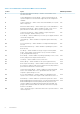

Table 1. Server Administrator Instrumentation MIB Sections in This Guide
Section Topics MIB Group Numbers
2 Instrumentation MIB Version Group — defines version numbers of the
Instrumentation MIB
1
3 Systems Management Software Group — defines information about the
systems management software and the supported systems management
standards
100
4 System State Group — defines status, state, and redundancy for a system
and its components
200
5 Chassis Information Group — defines chassis types, events, and indicators 300
6 Operating System Group — defines variables for name, version, service
pack, and other information about a system’s operating system
400
7 System Resource Group — defines variables for input/output ports,
memory, interrupts, and direct memory access
500
8 Power Group — defines variables for power units, power supplies, and their
current and voltage probes
600
9 Thermal Group — defines variables for temperature probes and cooling
devices
700
10 User Security Group — defines variables for creating and modifying user
accounts
800
11 Remote Flash BIOS Group — defines variables for updating the system’s
BIOS remotely
900
12 Port Group — defines variables for major port types such as keyboard,
monitor, small computer system interface (SCSI), Universal Serial Bus
(USB), and parallel and serial ports
1000
13 Device Group — defines variables for pointing, keyboard, processor, cache,
memory, and personal computer interface devices
1100
14 Slot Group — defines variables for the system’s slots 1200
15 Memory Group — defines variables for the system’s physical memory 1300
16 BIOS Setup Control Group — defines variables for BIOS functions such as
boot sequence, speakers, Wake on the local area network (LAN), diskettes,
ports, and network interface controllers (NIC)
1400
17 Local Response Agent Group — defines variables for global settings and
actions. These variables allow users to predetermine how the system
responds to a particular type of event
1500
18 Cost of Ownership Group — defines variables for tracking data on the
system’s service contract, lease, repair records, trouble tickets, and so on
1600
20 Cluster Group — defines variables for systems that operate as a cluster 1800
21 Baseboard Management Controller Group — provides information about the
Baseboard Management Controller (BMC) that may be present in your
system. In addition to providing general information about the BMC, this
group provides information about the serial and local area network (LAN)
interfaces of the BMC
1900
26 Traps — defines the types of alerts that can be sent to report the status of
critical components
5000
8 Introduction