
SNMP Reference Guide
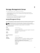

Syntax DellStatus
Access Read-only
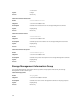
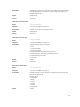
Table 1434. Agent Smart Thermal Shutdown
Name
agentSmartThermalShutdown
Object ID 1.3.6.1.4.1.674.10893.1.20.110.15
Description Indicates the status of smart thermal shutdown for PowerVault 220S
and PowerVault 221S enclosures.
Possible values:
1: Enabled
2: Disabled
3: Not applicable
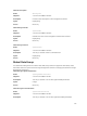
Syntax Integer
Access Read-only
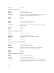
Physical Devices Group
The Physical Devices MIB group provides information about the devices managed by the Storage
Management software and their relationships to each other. The following MIB tables define objects and
relationships (connections) among the objects.
• Controller Table — describes available properties for each controller on the managed system.
• Channel Table — describes available properties for each channel on the managed system.
• Enclosure Table — describes available properties for each enclosure on the managed system.
• Array Disk Table — describes available properties for each physical array disk on the managed system.
• Array Disk Enclosure Connection Table — describes the connections between Fibre Channel array
disks, their enclosure, and their associated controller. For each object in the table, its object number
corresponds to an instance number in the appropriate MIB table for that object where all of the object
properties can be found.
• Array Disk Channel Connection Table — describes the connections between SCSI array disks, their
channel, and their associated controller. For each object in the table, its object number corresponds
to an instance number in the appropriate MIB table for that object where all of the object properties
can be found.
• Fan Table — describes available properties for each fan on the managed system.
• Fan Connection Table — describes the connection between each fan on the managed system and its
enclosure. Each enclosure number in the table corresponds to that enclosure instance in the
Enclosure Table.
• Power Supply Table — describes available properties for each power supply on the managed system.
• Power Supply Connection Table — describes the connection between each power supply on the
managed system and its enclosure. Each enclosure number in the table corresponds to that enclosure
instance in the Enclosure Table.
• Temperature Probe Table — describes available properties for each temperature probe on the
managed system.
• Temperature Probe Connection Table — describes the connection between each temperature probe
on the managed system and its enclosure. Each enclosure number in the table corresponds to that
enclosure instance in the Enclosure Table.
• EMM Table — describes available properties for each Enclosure Management Module (EMM) on the
managed system.
377