
User's Manual


l Complete Create Virtual Disk Advanced Wizard (Step 2 of 4). In this step, you select the channels and the disks to be used by the virtual disk. The
selections you make determine whether or not the virtual disk is channel- redundant.
There are specific RAID level and configuration requirements for implementing channel redundancy. You must select the same number of physical disks
on each channel that you use. For information on the number of physical disks that can be used for different RAID levels, see Number of Physical Disks
per Virtual Disk. For information on controller-specific implementations of the RAID levels, see Controller-supported RAID Levels.
To complete Create Virtual Disk Advanced Wizard (Step 2 of 4), see Physical disk Selection for Channel-redundant Virtual Disks on PERC 4/DC, 4e/DC,
4/Di, and 4e/Di Controllers depending on the type of the controller.
Physical disk Selection for Channel-redundant Virtual Disks on PERC 4/DC, 4e/DC, 4/Di, and 4e/Di Controllers
The following sections describe creating a channel-redundant virtual disk using RAID 10 or RAID 50 on a PERC 4/DC, 4e/DC, 4/Di, or 4e/Di, controllers.
RAID 10
a. Select one physical disk on each of two channels. (In other words, each of the two channels select a single disk.)
b. Select an additional disk on each of the two channels. You have now selected the minimum number of disks for a RAID 10.
c. Repeat step b until you have the desired number of disks.
d. Click Continue.
RAID 50
a. Select one physical disk on each of three channels. (In other words, each of the three channels select a single disk.)
b. Select an additional disk on each of the three channels. You have now selected the minimum number of disks for a RAID 50. Continue selecting a
disk on each channel until you have selected the desired number of disks.
c. Repeat step b until you have the desired number of disks.
d. Click Continue.
Connector Health
This screen displays the status of the connector and the components attached to the connector.
Connector Status
Component status is indicated by the severity. A component with a Warning or Critical/Failure status requires immediate attention to avoid data loss if
possible. A component's status may indicate the combined status of the component and its lower-level objects. For more information, see Determining the
Health Status for Storage Components.
It may be useful to review the Alert Log for events indicating why a component has a Warning or Critical status. For additional troubleshooting information,
see Troubleshooting.
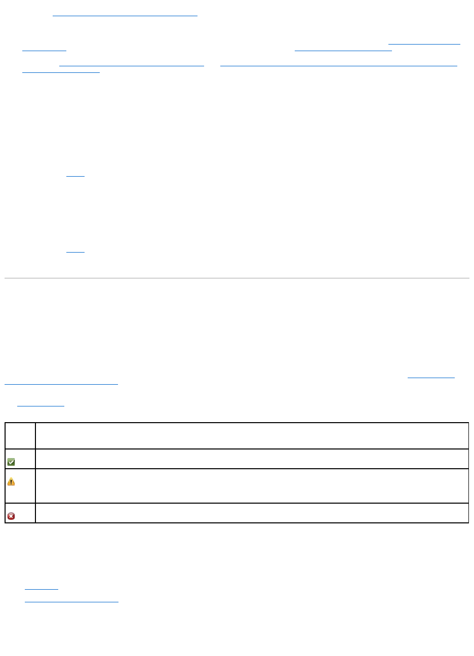
Table 8-1. Component Severity
Connector Information
For information on the connector, see the following topics:
l Connectors
l Connector Properties and Tasks
Connector Components
For information on attached components, see the following topic:
Severity
Component Status
Normal/OK. The component is working as expected.
Warning/Non-critical. A probe or other monitoring device has detected a reading for the component that is above or below the acceptable level.
The component may still be functioning, but it could fail. The component may also be functioning in an impaired state. Data loss is possible.
Critical/Failure/Error. The component has either failed or failure is imminent. The component requires immediate attention and may need to be
replaced. Data loss may have occurred.