Dell OpenManage Server Administrator Storage Management User's Guide Overview Getting Started Understanding RAID Concepts Quick Access to Storage Status and Tasks Storage Information and Global Tasks Controllers RAID Controller Batteries Connectors Enclosures and Backplanes Virtual Disks Physical Disks Protecting Your Virtual Disk with a Hot Spare Moving Physical and Virtual Disks from One System to Another CacheCade Using Solid State Drives BIOS Terminology Troubleshooting Frequently Asked Questions Suppo
Back to Contents Page Supported Features Dell OpenManage Server Administrator Storage Management User's Guide Supported Features on the PERC 4/SC, 4/DC, 4/Di, 4e/Si, 4e/Di, 4e/DC, and 4/IM Controllers Supported Features on the CERC SATA1.5/2s and CERC SATA1.
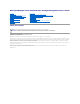
NOTE: For PERC 4 controllers, (Manual mode is not available). Start Patrol Read No No No No No No No Stop Patrol Read No No No No No No No Battery Tasks Table A-2.
Rename Yes Yes Yes Yes Yes Yes Yes Blink/Unblink Yes Yes Yes Yes Yes Yes Yes Reconfigure Yes Yes Yes Yes Yes Yes No Change Policy Yes Yes Yes Yes Yes Yes No Split Mirror No No No No No No No Unmirror No No No No No No No Delete Last Virtual Disk Yes Yes Yes Yes Yes Yes No Delete (any) Virtual Disk Yes Yes Yes Yes Yes Yes No Check Consistency Yes Yes Yes Yes Yes Yes No Cancel Check Consistency Yes Yes Yes Yes Yes Yes No Pause Che
RAID Level PERC 4/SC PERC 4/DC PERC 4/DI PERC 4e/SI PERC 4e/DI PERC 4e/DC PERC 4/IM Concatenation Yes Yes Yes Yes Yes Yes No RAID 0 Yes Yes Yes Yes Yes Yes No RAID 1 Yes Yes Yes Yes Yes Yes Yes RAID 5 Yes Yes Yes Yes Yes Yes No RAID 10 Yes Yes Yes Yes Yes Yes No RAID 50 Yes Yes Yes Yes Yes Yes No RAID 6 No No No No No No No RAID 60 No No No No No No No Read, Write, and Disk Cache Policy Table A-8.
Controller Tasks Table A-10. Controller Tasks Supported by the CERC SATA1.5/2s and CERC SATA1.5/6ch Controllers Controller Task Name CERC SATA 1.5/2s CERC SATA 1.
Cancel Rebuild No No Remove Dead Disk Segments No Yes Format Disk No No Clear No No Cancel Clear No No Virtual Disk Tasks Table A-14. Virtual Disk Tasks Supported by the CERC SATA1.5/2s and CERC SATA1.
Minimum Number of Physical Disks that Can Be Concatenated 1 1 Minimum Number of Physical Disks in a RAID 0 1 1 Minimum Number of Physical Disks in a RAID 1 2 2 Minimum Number of Physical Disks in a RAID 5 NA 3 Minimum Number of Physical Disks in a RAID 10 NA 4 Minimum Number of Physical Disks in a RAID 50 NA NA Maximum number of physical disks in a RAID 6 NA NA Maximum number of physical disks in a RAID 60 NA NA Minimum number of physical disks in a RAID 6 NA NA Minimum number of
Supported Features on the PERC 5/E, PERC 5/i, PERC 6/E, PERC 6/I, PERC 6/I Modular, and CERC 6/I Controllers This section identifies the controller-supported features and whether or not an enclosure can be attached to the controller.
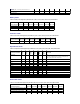
Check Consistency Report Yes Yes Yes Yes Yes Yes Slot Occupancy Report Yes Yes Yes Yes Yes Yes Battery Tasks Table A-20.
Blink/Unblink Yes Yes Yes Yes Yes Yes Reconfigure Yes Yes Yes Yes Yes Yes Change Policy Yes Yes Yes Yes Yes Yes Split Mirror No No No No No No Unmirror No No No No No No Delete Last Virtual Disk Yes Yes Yes Yes Yes Yes Delete (any) Virtual Disk Yes Yes Yes Yes Yes Yes Check Consistency Yes Yes Yes Yes Yes Yes Cancel Check Consistency Yes Yes Yes Yes Yes Yes Pause Check Consistency No No No No No No Resume Check Consistency No No No No
RAID Level PERC 5/E PERC 5/I PERC 6/E PERC 6/I PERC 6/I Modular CERC 6/I Concatenation No No No No No No RAID 0 Yes Yes Yes Yes Yes Yes RAID 1 Yes Yes Yes Yes Yes Yes RAID 5 Yes Yes Yes Yes Yes Yes RAID 10 Yes Yes Yes Yes Yes Yes RAID 50 Yes Yes Yes Yes Yes Yes RAID 6 No No Yes Yes Yes Yes RAID 60 No No Yes Yes Yes Yes Read, Write, Cache and Disk Cache Policy Table A-26.
For enclosure-supported tasks, see Enclosure and Backplane Features. Controller Tasks Table A-28.
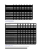
Table A-30. Connector Tasks Supported by the PERC H800, PERC H700 Adapter, PERC H700 Integrated, and PERC H700 Modular Controllers Connector Task Name PERC H800 PERC H700 Adapter PERC H700 Integrated PERC H700 Modular Connector Rescan No No No No Physical Disk Tasks Table A-31.
Slow Initialize Virtual Disk Yes Yes Yes Yes Cancel Initialize Virtual Disk Yes Yes Yes Yes Replace Member Yes Yes Yes Yes Encrypt Virtual Disk Yes Yes Yes Yes Clear Virtual Disk Bad Blocks Yes Yes Yes Yes Virtual Disk Specifications Table A-33.
Read, Write, and Cache Policy PERC H800 PERC H700 Adapter PERC H700 Integrated PERC H700 Modular Cache settings Yes Yes Yes Yes Read Policy Yes Yes Yes Yes Read Ahead (Enabled) Yes Yes Yes Yes Adaptive Read Ahead Yes Yes Yes Yes No Read Ahead (Disabled) Yes Yes Yes Yes Write Policy Yes Yes Yes Yes Write Back (Enabled) Yes Yes Yes Yes Write Through (Disabled) Yes Yes Yes Yes Force Write Back (Enabled Always) Yes Yes Yes Yes Write Cache Enabled Prot
Set Check Consistency Rate No No No Set Reconstruct Rate No No No Rescan Controller No No No Create Virtual Disk No Yes Yes Export Log File No No No Clear Foreign Configuration Yes Yes Yes Import Foreign Configuration No Yes Yes Import/Recover Foreign Configuration No Yes Yes Set Patrol Read Mode No No No Start Patrol Read No No No Stop Patrol Read No No No Patrol Read Report No No No Check Consistency Report No No No Slot Occupancy Report Yes Yes Yes C
Segments Format Disk No No No Clear No No No Cancel Clear No No No Virtual Disk Tasks Table A-41.
Maximum Number of Physical Disks per Span 4 10 10 Minimum Stripe Size 64k 64k 64k Maximum Stripe Size 64k 64k 64k Maximum Number of Virtual Disks per Disk Group 1 1 1 Maximum Number of Physical Disks that Can Be Concatenated NA NA NA Maximum Number of Physical Disks in a RAID 0 4 8 10 - Adapter 10 - Integrated 4 - Modular Maximum Physical Disks in a RAID 1 2 2 2 Maximum Number of Physical Disks in a RAID 5 NA NA NA Maximum Number of Physical Disks in a RAID 10 NA NA 10 - A
Supported Features on the PERC S100 and S300 Controllers This section identifies the controller-supported features and whether or not an enclosure can be attached to the controller. l Controller Tasks l Physical Disk Tasks l Virtual Disk Tasks l Virtual Disk Specifications l Supported RAID Levels l Read, Write, Cache and Disk Cache Policy l Enclosure Support Controller Tasks Table A-46.
Maximum Virtual Disk Size None None Maximum Number of Spans per Virtual Disk NA NA Maximum Number of Physical Disks per Span NA NA Minimum Stripe Size 64k 64k Maximum Stripe Size 64k 64k Maximum Number of Virtual Disks per Physical Disk 8 8 Maximum Number of Physical Disks that Can Be Concatenated NA NA Maximum Number of Physical Disks in a RAID 0 8 8 Maximum Physical Disks in a RAID 1 2 2 Maximum Number of Physical Disks in a RAID 5 8 8 Maximum Number of Physical Disks in a RAI
Enclosure Support PERC S100 PERC S300 Can an enclosure be attached to this controller? No No Supported Features on the Non-RAID Controllers This section identifies the controller-supported features and whether or not an enclosure can be attached to the controller. l Controller Tasks l Battery Tasks l Connector Tasks l Physical Disk Tasks l Virtual Disk Tasks l Enclosure Support For enclosure-supported tasks, see Enclosure and Backplane Features.
Connector Task Name Non-RAID SCSI Non-RAID SAS Connector Rescan No No Physical Disk Tasks Table A-56.
Table A-58. Enclosure Support on the Non-RAID Controllers Enclosure Support Non-RAID SCSI Non-RAID SAS Can an enclosure be attached to this controller? Yes No Enclosure and Backplane Features This section identifies the features supported by the enclosure or backplane.
Shutdown Table A-62. Backplane Support for Smart Thermal Shutdown Smart Thermal Shutdown SCSI SAS Smart Thermal Shutdown No No Maximum Supported Configuration Table A-63.
Determining the Health Status for Storage Components Dell OpenManage Server Administrator Storage Management User's Guide Health Status Rollup: Battery is Charging or Dead Health Status Rollup: Physical Disks in a Virtual Disk are Failed or Removed Health Status Rollup: Physical Disks in a Virtual Disk are Unsupported, Partially or Permanently Degraded Health Status Rollup: All Physical Disks in a Virtual Disk are in Foreign State Health Status Rollup: Some Physical Disks in a Virtual Disk are in
Table B-3. Health Status Rollup: Physical Disks in a Virtual Disk are Unsupported, Partially or Permanently Degraded (Enclosures Not Included) Storage Subsystem Controller Battery Connector Physical Disk(s) Firmware/ Virtual Disk(s) Driver Component Status Health Rollup Health Status Rollup: All Physical Disks in a Virtual Disk are in Foreign State Table B-4.
Health Status Rollup: Virtual Disk is Failed Table B-7. Health Status Rollup: Virtual Disk is Failed (Enclosures Not Included) Storage Subsystem Controller Battery Connector Physical Disk(s) Firmware/Driver Virtual Disk(s) Component Status Health Rollup Health Status Rollup: Unsupported Firmware Version Table B-8.
Health Rollup NA Health Status Rollup: One Enclosure Temperature Probe is Failed Table B-12. Health Status Rollup: One Enclosure Temperature Probe is Failed Storage Subsystem Controller Connector Enclosure Enclosure Temperature Probe Virtual Disks Physical Disks Component Status Health Rollup NA Health Status Rollup: Lost Both Power Connections to the Enclosure Table B-13.
Health Status Rollup: Physical Disk is Rebuilding Table B-15.
Back to Contents Page Physical Disks Dell OpenManage Server Administrator Storage Management User's Guide Guidelines to Replace a Physical Disk Add a New Disk to Your System How to Avoid Removing the Wrong Disk Replacing a Physical Disk Receiving SMART Alerts Other Disk Procedures Physical Disk Properties and Tasks Blink and Unblink (Physical Disk) Remove Dead Segments Prepare to Remove Initialize Rebuild Cancel Rebuild Assign and Unassign Global Hot Spare Online and Offline
The new physical disk should be displayed in the tree view after refreshing the display. If the new disk is not displayed, restart the computer. Related Information l If you are replacing a disk that is part of a virtual disk, see Replacing a Failed Disk. l If you want to include the new disk in a virtual disk, see Virtual Disk Considerations for PERC 4/SC, 4/DC, 4e/DC, 4/Di, 4e/Si, 4e/Di, PERC 5/E, PERC 5/i, PERC 6/E, and PERC 6/I Controllers or Virtual Disk Considerations for CERC SATA1.
Other Disk Procedures l Replacing a Failed Disk l Recovering from Removing the Wrong Physical Disk l Moving Physical and Virtual Disks from One System to Another l Troubleshooting Physical Disk Properties and Tasks Use this window to view information about physical disks and execute physical disk tasks. Physical Disk Properties The following table describes properties that may be displayed for physical disks depending on the controller. Table 11-1.
Clear—The Clear task is being performed on the physical disk. A physical disk may also display the Clear state if the physical disk is a member of a virtual disk that is being slow initialized. For more information, see Clear Physical Disk and Cancel Clear and Format and Initialize; Slow and Fast Initialize. SMART Alert Detected—A SMART alert (predictive failure) has been detected on the physical disk. The physical disk may fail and should be replaced.
Serial No. This property displays the disk's serial number. Part Number This property displays the Piece Part Identification (PPID) of the physical drive. Negotiated Speed This property displays the speed of data transfer that the disk negotiated while spinning up and upon initial communication with the controller.
NOTE: The Blink and Unblink tasks are only supported for hotswap physical disks (disks that reside in a carrier). When using an LSI PCI-e U320 controller, the Blink and Unblink tasks apply to physical disks contained in carriers that can be inserted into a server or an enclosure. If the physical disk is not contained in a carrier but is instead designed to be connected with a SCSI cable (typically a ribbon cable), then the Blink and Unblink tasks are disabled.
Cancel Rebuild Does my controller support this feature? See Supported Features. Use the Cancel Rebuild task to cancel a rebuild that is in progress. If you cancel a rebuild, the virtual disk remains in a degraded state. The failure of an additional physical disk can cause the virtual disk to fail and may result in data loss. It is recommended that you rebuild the failed physical disk as soon as possible.
2. Click Online or Offline when ready or click Go Back to Previous Page. To locate this task in Storage Management: 1. Expand the Storage tree object to display the controller objects. 2. Expand a controller object. 3. Expand a Connector object. 4. Expand the enclosure or Backplane object. 5. Select the Physical Disks object. 6. Select Online or Offline from the Available Tasks drop-down menu of the physical disk you want to make online or offline. 7. Click Execute.
and if you have enabled the revertible hot spare task, the data is copied from the erstwhile hot spare to the new disk. You can also use the Revertible Hot Spare task to copy data from a physical disk to the hot spare on a predictive failure event. If Revertible Hot Spare is enabled and the physical disk is SMART-enabled, the controller firmware automatically starts copying data from the SMART-enabled disk in the virtual disk to the hot spare.
Back to Contents Page RAID Controller Batteries Dell OpenManage Server Administrator Storage Management User's Guide Battery Properties and Tasks Some RAID controllers have batteries. If the controller has a battery, Storage Management displays the battery under the controller object in the tree view. In the event of a power outage, the controller battery preserves data that is in the nonvolatile cache memory (NVRAM) but not yet written to disk.
State This property displays the current status of the battery. Possible values are: Ready—The battery is functioning normally. Degraded—The battery needs to be reconditioned. Reconditioning—The battery is being reconditioned. For more information, see Recondition Battery. Charging—The battery is undergoing the recharge phase of the battery learn cycle. For more information, see Start Learn Cycle. Learning—The battery is undergoing the discharge phase of the battery learn cycle.
Drop-down Menu Battery Tasks: l Recondition Battery l Start Learn Cycle l Battery Delay Learn Cycle Recondition Battery Does my controller support this feature? See Supported Features. Some controllers have NiMHi batteries which need to be reconditioned approximately every six months to maintain reliability. This reconditioning cycle requires a full discharge and recharge of the battery.
Battery Delay Learn Cycle Does my controller support this feature? See Supported Features. The controller firmware automatically initiates the battery learn cycle every 90 days. Although you cannot stop the firmware from running the Learn cycle, you can delay the start time of the learn cycle for up to seven days. For more information on the battery learn cycle, see Start Learn Cycle. To delay the battery learn cycle: 1. Type a numerical value in the Days text box.
Back to Contents Page BIOS Terminology Dell OpenManage Server Administrator Storage Management User's Guide BIOS Terms and the PERC 4/SC, 4/DC, 4e/DC, and 4/Di Controllers BIOS Terms and the CERC SATA1.5/6ch and CERC SATA1.5/2s Controllers The terminology used by Storage Management can be different from the terminology used in the controller BIOS. The following sections show some of these differences. BIOS Terms and the PERC 4/SC, 4/DC, 4e/DC, and 4/Di Controllers Table 15-1.
Back to Contents Page Connectors Dell OpenManage Server Administrator Storage Management User's Guide Channel Redundancy and Thermal Shutdown Channel Redundancy on PERC 4/DC, 4e/DC, 4/Di, and 4e/Di Controllers Creating a Channel-redundant Virtual Disk Connector Health Connector Properties and Tasks Logical Connector Properties and Tasks A controller contains one or more connectors (channels or ports) to which you can attach disks.
3. Complete Create Virtual Disk Advanced Wizard (Step 2 of 4). In this step, you select the channels and the disks to be used by the virtual disk. The selections you make determine whether or not the virtual disk is channel- redundant. There are specific RAID level and configuration requirements for implementing channel redundancy. You must select the same number of physical disks on each channel that you use.
For information on attached components, see the following topic: Enclosures and Backplanes l Connector Properties and Tasks Use this window to view information about the connector and execute connector tasks. Connector Properties The connector properties can vary depending on the model of the controller. Connector properties may include: Table 8-2. Connector Properties Property Definition These icons represent the severity or health of the storage component.
5. Select Rescan from the Available Tasks drop-down menu. 6. Click Execute. Connector Components For information on attached components, see the following topic: l Enclosure and Backplane Properties and Tasks Logical Connector Properties and Tasks Use this window to view information about the logical connector (connector in redundant path mode) and to execute connector tasks. Logical Connector Properties The connector properties can vary depending on the model of the controller.
l Enclosure and Backplane Properties and Tasks Back to Contents Page
Back to Contents Page Controllers Dell OpenManage Server Administrator Storage Management User's Guide What is a Controller? RAID Controller Technology: SCSI, SATA, ATA, and SAS RAID Controller Features Controller-supported RAID Levels Controller-supported Stripe Sizes RAID Controller Read, Write, Cache, and Disk Cache Policy Cluster-enabled RAID Controllers Creating and Deleting Virtual Disks on Cluster-enabled Controllers Integrated Mirroring and the PERC 4/IM Controller Background
The following RAID controllers use Serial Attached SCSI (SAS) technology. l PERC 5/E l PERC 5/i Integrated l PERC 5/i Adapter l SAS 5/iR Integrated l SAS 5/iR Adapter l PERC 6/E l PERC 6/I controller family l SAS 6/iR controller family l PERC S100 and S300 controllers l PERC H200, H700, and H800 controllers RAID Controller Features Different controllers have different features.
Read Policy Does my controller support this feature? See Supported Features The read policies indicate whether or not the controller should read sequential sectors of the virtual disk when seeking data. l Read-Ahead—When using read-ahead policy, the controller reads sequential sectors of the virtual disk when seeking data. Read-ahead policy may improve system performance if the data is actually written to sequential sectors of the virtual disk.
controller cache. The direct I/O setting does not override the cache policy settings. Direct I/O is also the default setting. NOTE: Cache policy is not supported on any controller that does not have a battery. Disk Cache Policy Does my controller support this feature? See Supported Features. Set the physical disk caching policy of all members of a Virtual Disk by enabling the Disk Cache Policy.
1. Stop the clustering services on system B. 2. Turn off system B. 3. Create or delete the virtual disk on system A. For more information on creating and deleting virtual disks, see: ¡ Considerations Before Creating Virtual Disks ¡ Creating Virtual Disks ¡ Virtual Disk Task: Delete 4. Reboot system A. 5. Restart system B. Integrated Mirroring and the PERC 4/IM Controller The PERC 4/IM controller enables you to mirror a physical disk that resides internally in the server.
Firmware/Driver Versions Use this window to view information about the controller firmware and drivers. For more information on firmware and drivers, see Before Installing Storage Management. Firmware/Driver Properties The firmware and driver properties can vary depending on the model of the controller. On some controllers, Storage Management may not be able to obtain the driver or firmware version. In this case, Storage Management displays Not Applicable.
Controller Information For information on the controller, see the following topics: l Controllers l Controller Properties and Tasks Controller Components For information on attached components, see the following topics: l RAID Controller Batteries l Firmware/Driver Versions l Connectors NOTE: If you have connected the enclosure in Redundant path mode, the connectors are represented as Logical Connector.
NOTE: On some controllers, Storage Management may not be able to obtain the driver version. In this case, Storage Management displays Not Applicable. Minimum Required Driver Version This property displays the minimum driver version that is required by Storage Management. This property is only displayed if the controller driver does not meet the minimum requirement. The firmware and drivers listed in the Readme file refer to the minimum supported version for these controllers.
NOTE: Any drive in the slot functions as a hot spare. If the drive contains foreign data, it is overwritten. Disabled: The slot corresponding to the hot spare drive is not persistent. If the drive is removed from the slot and any drive is inserted, the slot stops function as a hot spare. You need to manually assign the drive as a hot spare again. Controller Tasks Enables you to configure and manage the controller. For more information, see Controller Tasks:.
3. Select the Information/Configuration subtab. 4. Select a report from the Select Report drop-down menu. 5. Click Execute. Available Reports l Patrol Read Report l Check Consistency Report l Slot Occupancy Report Rescan Controller Does my controller support this feature? See Supported Features. On SCSI controllers, a rescan updates configuration changes (such as new or removed devices) for all components attached to the controller.
Quiet Alarm (Controller) Does my controller support this feature? See Supported Features. Use the Quiet Alarm task to quiet the controller's alarm when it is sounding. After it is quieted, the alarm is still enabled in the event of a future device failure. Test Alarm (Controller) Does my controller support this feature? See Supported Features. Use the Test Alarm task to test whether the controller alarm is functional. The alarm sounds for about 2 seconds.
Does my controller support this feature? See Supported Features. The Set Rebuild Rate task changes the controller's rebuild rate. During a rebuild, the complete contents of a physical disk are reconstructed. The rebuild rate, configurable between 0% and 100%, represents the percentage of the system resources dedicated to rebuilding failed physical disks.
To locate this task in Storage Management: 1. Expand the Storage tree object to display the controller objects. 2. Select a controller object. 3. Select the Information/Configuration subtab. 4. Select Reset Configuration from the Available Tasks drop-down menu. 5. Click Execute. You can also locate this task from the Change Controller Properties drop down menu. For more information, see Change Controller Properties.
enter the corresponding Passphrase to unlock the drives. l If any foreign configurations locked using Dell Key Manager (DKM) are detected, the storage controller attempts to unlock the disks automatically by connecting to the DKM server. If the DKM foreign configuration cannot be unlocked for any reason, the corresponding error message is displayed.
To preview the import of foreign configuration Click Foreign Configuration Operations from the Controller Tasks drop down menu. Click Execute to display the Foreign Configuration Preview screen. To locate this task in Storage Management For SAS controllers with firmware version 6.1: 1. Expand the Storage tree object to display the controller objects. 2. Select a controller object. 3. Select the Information/Configuration subtab. 4.
3. Select the Information/Configuration subtab. 4. Select Foreign Configuration Operations from the Controller Available Tasks drop-down menu. 5. Click Execute. 6. On the Foreign Configuration Preview page, click Import/Recover. For controllers with firmware version 6.0 and earlier: 1. Expand the Storage tree object to display the controller objects. 2. Select a controller object. 3. Select the Information/Configuration subtab. 4.
The Physical Disks in Foreign Virtual Disks page displays the physical disks and the dedicated hot spare, if any, included in the foreign configuration. The following table describes properties for physical disks in the foreign configuration. Table 6-5. Physical disk Properties Property Definition Status These icons represent the severity or health of the storage component. Normal/OK Warning/Non-critical Critical/Fatal For more information, see Storage Component Severity.
Unknown—Storage Management is unable to determine the media type of the physical disk. Used RAID Disk Space This property displays how much of the physical disk space is being used by the virtual disks on the controller. This property is not applicable for physical disks attached to non-RAID controllers. In certain circumstances, the Used RAID Disk Space displays a value of zero (0) even though a portion of the physical disk is actually being used. This occurs when the used space is 0.005 GB or less.
5. Click Execute. You can also locate this task from the Change Controller Properties drop down menu. For more information, see Change Controller Properties. Set Check Consistency Rate Does my controller support this feature? See Supported Features. The Set Check Consistency Rate task changes the amount of system resources dedicated to the check consistency task. See Check Consistency for more information about the check consistency task.
2. Click Apply Changes. To exit and cancel your changes, click Go Back to Previous Page. To locate this task in Storage Management: 1. Expand the Storage tree object to display the controller objects. 2. Select a controller object. 3. Select the Information/Configuration subtab. 4. Select Set Reconstruct Rate from the Available Tasks drop-down menu. 5. Click Execute. You can also locate this task from the Change Controller Properties drop down menu.
Available Available Available Disconnected Disconnected Available However, if the communication channel between any two enclosures is lost, the redundant path configuration is degraded and the health of the logical connector is displayed as degraded. For a brief outline of this scenario, see Table 6-7. Table 6-7.
¡ A background initialization ¡ A check consistency In addition, the Patrol Read suspends during heavy I/O activity and resumes when the I/O is finished. To set the Patrol Read mode: Click the radio button for the Patrol Read mode setting that you want to select: The possible settings are: l Auto—Setting the mode to Auto initiates the Patrol Read task. When the task is complete, it automatically runs again within a specified period of time.
5. Click Execute. You can also locate this task from the Change Controller Properties drop down menu. For more information, see Change Controller Properties. Related Information: l Set Patrol Read Mode Change Controller Properties Does my controller support this feature? See Supported Features. The Change Controller Properties task provides you the option to change multiple controller properties simultaneously. This task is available only on SAS controllers with firmware version 6.1 and later.
l Revertible Hot Spare l Loadbalance l Redundant Path Configuration Manage Physical Disk Power Does my controller support this feature? See Supported Features. The Manage Physical Disk Power task allows you to manage the power consumed by the physical disks by spinning down the hot spares and unconfigured disks. This option is provided only with PERC H700 and PERC H800 controllers with the firmware version 7.1 and above.
l Cables to any virtual disk are not disconnected. Manage Encryption Key NOTE: To configure encryption, you do not require an SED. However, to create a secure virtual disk, you require an SED. The encryption settings are then used to configure the virtual disk and the SED. On an encryption-capable controller, the Manage Encryption Key task allows you to enable encryption in LKM mode or DKM mode. You can enable either LKM mode or DKM mode at a time.
1. Go to the Manage Encryption key window and select the Enable Dell Key Management (DKM) Server radio button. 2. Click Apply Changes. The controller Information/Configuration tab now displays Encryption Key Present as Yes and Encryption Mode as DKM. NOTE: The Enable Dell Key Management (DKM) option is available only when the system is running a DKM-capable BIOS and iDRAC firmware. Rekeying the Encryption Key To change the DKM key: 1.
Changing or Deleting the Encryption Key You can change an Encryption Key of a controller if the controller already has a configured Encryption Key. You can delete an Encryption Key for encrypted controllers only if there are no encrypted virtual disks. To change the Encryption Key, enter the New Encryption Key Identifier and Passphrase. You are prompted to authenticate with the current Passphrase.
1. Click Storage to view the dash board. 2. Select View Patrol Read Report from the Select Report drop-down menu. 3. Click Execute. Check Consistency Report Does my controller support this feature? See Supported Features. This report provides information on all the Consistency Checks done on the controller in a chronological order. It provides information such as last run time and result. If the Consistency Check fails, it provides the reason for the failure.
Back to Contents Page CacheCade Using Solid State Drives Dell OpenManage Server Administrator Storage Management User's Guide Manage CacheCade CacheCade is used to improve random read performance of the Hard Disk Drive (HDD) based Virtual Disks. A solid-state drive (SSD) is a data storage device that uses solid-state memory to store persistent data. SSDs significantly increase the I/O performance (IOPS) and/or write speed in Mbps from a storage device.
Resizing the CacheCade To resize the CacheCade: 1. In the CacheCade(s) screen, go to the CacheCade that you want to resize and select Resize ... from the Tasks drop-down menu. The Resize CacheCade(s) screen is displayed. 2. From the available CacheCade(s), add or remove additional CacheCade(s) as required. The disks that you select are displayed in the Selected Physical Disks section.
Size This property provides the size of the CacheCade. Bus Protocol This property displays the technology that the physical disk is using. Possible values are SAS and SATA. Disk Cache Policy This property displays whether the disk cache policy of the physical disks that are part of the CacheCade is Enabled or Disabled. See RAID Controller Read, Write, Cache, and Disk Cache Policy.
Back to Contents Page Enclosures and Backplanes Dell OpenManage Server Administrator Storage Management User's Guide Backplanes Enclosures SMART Thermal Shutdown Changing the Mode on PowerVault 220S and PowerVault 221S Enclosures Enclosure Management Enclosure and Backplane Health Enclosure and Backplane Properties and Tasks Set Asset Data Set Temperature Probe Values View Slot Occupancy Report EMM Properties Fan Properties Power Supply Properties Temperature Probe Properties
Enclosure Fans The fans are a component of the enclosure's cooling module. The fans are displayed by expanding the enclosure object in the tree view. You can select the Fans object to display their status information. Enclosure Power Supplies The enclosure's power supplies are displayed under the Power Supplies object in the tree view. You can select the Power Supplies object to display their status information.
The PowerVault 220S and PowerVault 221S enclosures automatically turn off when their temperature reaches 55 degrees Celsius. This shutdown occurs whether or not you have implemented channel redundancy or have Storage Management installed. You can enable smart thermal shutdown using the command line interface. For more information, see the Dell OpenManage Server Administrator Command Line Interface User's Guide at support.dell.com/manuals.
l Enclosure and Backplane Properties and Tasks Enclosure and Backplane Components For information on attached components, see the following topics: l Physical Disks Enclosure and Backplane Properties and Tasks Use this window to view information about the enclosure or backplane and execute enclosure tasks. Enclosure and Backplane Properties The enclosure or backplane properties can vary depending on the model of the controller. Enclosure or backplane properties may include: Table 9-2.
Asset Name This property displays the name assigned to the enclosure. You can change this property using the Set Asset Data task. Backplane Part Number This property displays the part number of the enclosure's backplane. SAS Address This property displays the SAS address of the SAS backplane. Split Bus Part Number This property displays the part number of the enclosure's split bus module. A split bus is indicated by a single triangle symbol on the back of the enclosure.
Does my enclosure support this feature? See Supported Features. Use the Enable Alarm task to enable the enclosure alarm. When enabled, the audible alarm sounds whenever the fault LED lights. This may occur to signal events such as: l The enclosure temperature has exceeded the warning threshold. l A power supply, fan, or enclosure management module (EMM) has failed. l The split bus is not installed. (A split bus is indicated by a single triangle symbol on the back of the enclosure.
2. Identify a connector that is not attached to storage. If the connector is already attached to storage, then the Connector object can be expanded to display an enclosure or backplane and the attached physical disks. A Connector object that cannot be expanded in the tree view is an open connector not currently attached to storage. Storage Management displays a number for each connector. These numbers correspond to the connector numbers on the controller hardware.
1. 2. 3. Type the new asset tag name in the New asset tag text box. You can specify an inventory number or other useful information for your environment. The asset tag typically refers to the enclosure hardware. Type the new asset name in the New asset name text box. You can specify a name useful to you for organizing your storage environment. For example, the asset name could refer to the type of data stored on the enclosure or to the enclosure's location. Click Apply Changes.
5. Select the Information/Configuration subtab. 6. Select Set Temperature Probe Values from the Available Tasks drop- down menu. 7. Click Execute. View Slot Occupancy Report Does my controller support this feature? See Supported Features. The View Occupancy Slot Report task allows you to view empty and occupied slot details of the selected enclosure. It provides a diagram that represents the occupancy of physical drive slots.
of all environmental elements, such as temperature sensors, cooling modules, and power supplies. SCSI Terminator—The SCSI Terminator card is only used if the PowerVault 220S or PowerVault 221S enclosure is not configured with a redundant SCSI SES Module type of EMM. In systems equipped with two SCSI SES Modules, the SCSI termination is done through the EMMs. Firmware Version This property indicates the version of the firmware loaded on the EMM.
For more information, see Storage Component Severity. Name This property displays the name of the power supply. State This property displays the current status of the power supply. Ready—The power supply is functioning normally. Degraded—The power supply has encountered a failure and is operating in a degraded state. Failed—The power supply has encountered a failure and is no longer functioning. Storage Management may also be unable to communicate with the enclosure using SES commands.
Click the Set Temperature Probe button to launch the wizard for changing the temperature probe's Warning threshold. You can change the Warning threshold for each of the temperature probes included in the enclosure. For more information, see Set Temperature Probe Values. To launch the Set Temperature Probe wizard: 1. Expand the Storage tree object to display the controller objects. 2. Expand a controller object. 3. Expand a Connector object. 4. Expand the enclosure object. 5.
Back to Contents Page Frequently Asked Questions Dell OpenManage Server Administrator Storage Management User's Guide Why is a Rebuild not Working? How Can I Safely Remove or Replace a Physical Disk? How do I Recover from Removing the Wrong Physical Disk? How do I Identify the Firmware Version that is installed? Which Controllers do I Have? How do I Turn off an Alarm? Which RAID level is Best for me? This section provides frequently asked questions that address situations commonly experienc
Which Controllers do I Have? Each controller attached to the system is displayed under the Storage object in the tree view. In addition, the Storage object's Health and Information/Configuration subtabs display information for each controller. To identify which controllers are attached to the system: 1. Select the Storage tree view object. The Health subtab displays the name and status for each controller attached to the system. 2.
Back to Contents Page Getting Started Dell OpenManage Server Administrator Storage Management User's Guide Launching Storage Management User Privileges Using the Graphical User Interface Using the Storage Management Command Line Interface Displaying the Online Help Common Storage Tasks Dell OpenManage Server Administrator Storage Management is designed for system administrators who implement hardware RAID solutions and understand corporate and small business storage environments.
User and Power User privileges allow you to view storage status, but not manage or configure storage. With User and Power User privileges, you can use the omreport storage command and not the omconfig storage command. For more information on user groups and other Server Administrator security features, see the Dell OpenManage Server Administrator User's Guide.
l Assign a hot spare to the virtual disk—When a virtual disk uses a redundant RAID level, then you can assign a hot spare (backup physical disk) to rebuild data if a physical disk in the virtual disk fails. For more information, see: ¡ Protecting Your Virtual Disk with a Hot Spare—This section describes hot spares and includes controller-specific information. l Perform a Check Consistency—The Maintain Integrity of Redundant Virtual Disks task verifies the accuracy of a virtual disk's redundant data.
Back to Contents Page Protecting Your Virtual Disk with a Hot Spare Dell OpenManage Server Administrator Storage Management User's Guide Understanding Hot Spares Setting Hot Spare Protection Policy Considerations for Hot Spares on PERC 4/SC, 4/DC, 4e/DC, 4/Di, 4e/Si, 4e/Di, PERC 5/E, PERC 5/i, PERC 6/E, PERC 6/I, and CERC 6/I Controllers Considerations for Hot Spares on CERC SATA1.
Property Definition Enable Global Hot Spare Enables the Global Hot Spare Protection Policy. Minimum Number of Disks Displays the minimum number of physical disks to be assigned as global hot spares for the controller. Severity Level Displays the severity level that you must assign to the generated alert, if the Global Hot Spare policy is violated.
l Considerations for RAID 10, RAID 50, and RAID 60—If you have created a RAID 10 or RAID 50 virtual disk that does not fully consume its member physical disks, then you cannot assign a dedicated hot spare to the RAID 10 or RAID 50 virtual disk. Storage Management does not allow you to create RAID 10 and RAID 50 virtual disks from partial physical disks. You therefore do not encounter this situation if you use Storage Management to create your virtual disks.
To ensure that the controller firmware always has a healthy physical disk as a global hot spare, do the following: l When removing a physical disk that is assigned as a global hot spare, unassign the hot spare before removal and reassign another physical disk as the global hot spare. l Immediately replace any physical disk that has failed or been removed. This ensures that a healthy disk resides in a slot that the controller firmware assumes is a hot spare.
Back to Contents Page Moving Physical and Virtual Disks from One System to Another Dell OpenManage Server Administrator Storage Management User's Guide Required Conditions Migrating SCSI Virtual Disks to Another System Migrating SAS Virtual Disks to Another System This section describes how to move physical and virtual disks from one system to another.
Moving the Disks 1. 2. Turn off the system that the physical disks are being moved from. If the receiving controller has a preexisting virtual disk configuration on attached physical disks, use the following procedure for clearing the configuration: ¡ Turn off the receiving server. ¡ Remove all the physical disks from the controller. ¡ Start up the receiving server and clear the configuration from the controller BIOS.
Back to Contents Page Overview Dell OpenManage Server Administrator Storage Management User's Guide What's New in this Release? Before Installing Storage Management Supported Controllers Supported Enclosures Support for Disk and Volume Management Support for Encryption Key Management Dell OpenManage Server Administrator Storage Management provides enhanced features for configuring a system's locally-attached RAID and non-RAID disk storage.
l LinFlash l DellMgr l DellMON l LINLib l MegaMgr l MegaMON Prerequisite Drivers and Firmware on Linux Operating Systems On Linux operating systems, Storage Management installation is unable to detect whether the drivers and firmware on the system are at the required level for installing and using Storage Management. When installing on system running Linux operating systems, you can complete the installation regardless of whether the driver and firmware version meets the required level.
Storage Management supports the following non-RAID controllers.
Back to Contents Page Quick Access to Storage Status and Tasks Dell OpenManage Server Administrator Storage Management User's Guide Storage Dashboard and Storage Health Storage Health Hot Spare Protection Policy Select Report Storage Component Severity Storage Properties and Current Activity Alerts or Events Monitoring Disk Reliability on RAID Controllers Using Alarms to Detect Failures Using Enclosure Temperature Probes Rescan to Update Storage Configuration Changes Time Delay in
It may be useful to review the Alert Log for events indicating why a component has a Warning or Critical status. For additional troubleshooting information, see Troubleshooting. Table 4-1. Component Severity Severity Component Status Normal/OK—The component is working as expected. Warning/Non-critical—A probe or other monitoring device has detected a reading for the component that is above or below the acceptable level. The component may still be functioning, but it could fail.
Some storage components have alarms. When enabled, these alarms alert you when a component fails. For more information, see the following sections: l Enable Alarm (Controller) l Enable Alarm (Enclosure) Using Enclosure Temperature Probes Physical disk enclosures have temperature probes that warn you when the enclosure has exceeded an acceptable temperature range.
Related Information: l Rescan to Update Storage Configuration Changes Back to Contents Page
Back to Contents Page Storage Information and Global Tasks Dell OpenManage Server Administrator Storage Management User's Guide Storage Properties Global Tasks Storage Controllers Use this window to view high-level information about your system's storage. This window also enables you to launch global tasks that affect all controllers attached to the system. Storage Properties The Storage tree-view object has the following properties. Table 5-1.
4. Click Execute. Enable/Disable Smart Thermal Shutdown By default, the operating system and server are turned off when the PowerVault 220S and PowerVault 221S enclosures reach a critical temperature of 0 or 50 degrees Celsius. Using the Enable Smart Thermal Shutdown task, however, you can specify that only the enclosure, and not the operating system and server be turned off when the enclosure reaches a critical temperature.
Controllers in a cluster configuration should not have duplicate SCSI Initiator IDs. Refer to SCSI documentation for a list of acceptable SCSI Initiator ID values. On some controllers, this property is not available. In this case, this property displays as Not Applicable.
Back to Contents Page Understanding RAID Concepts Dell OpenManage Server Administrator Storage Management User's Guide What Is RAID? Organizing Data Storage for Availability and Performance Choosing RAID Levels and Concatenation Comparing RAID Level and Concatenation Performance No-RAID Storage Management uses Redundant Array of Independent Disks (RAID) technology to provide Storage Management capability.
RAID provides different methods or RAID levels for organizing the disk storage. Some RAID levels maintain redundant data so that you can restore data after a disk failure. Different RAID levels may also entail an increase or decrease in the system's I/O (read and write) performance. Maintaining redundant data requires the use of additional physical disks. As more disks become involved, the likelihood of a disk failure increases.
l Concatenates n disks as one large virtual disk with a capacity of n disks. l Data fills up the first disk before it is written to the second disk. l No redundancy data is kept. When a disk fails, the large virtual disk fails. l No performance gain. l No redundancy.
l Number of Physical Disks per Virtual Disk l Maximum Number of Virtual Disks per Controller RAID Level 1 (Mirroring) RAID 1 is the simplest form of maintaining redundant data. In RAID 1, data is mirrored or duplicated on one or more physical disks. If a physical disk on one side of the mirror fails, then the data can be rebuilt using the physical disk on the other side of the mirror. Figure 3-3.
RAID 5 Characteristics: l Groups n disks as one large virtual disk with a capacity of (n-1) disks. l Redundant information (parity) is alternately stored on all disks. l When a disk fails, the virtual disk still works, but it is operating in a degraded state. The data is reconstructed from the surviving disks. l Better read performance, but slower write performance. l Redundancy for protection of data.
l The virtual disk remains functional with up to two disk failures. The data is reconstructed from the surviving disks. l Better read performance, but slower write performance. l Increased redundancy for protection of data. l Two disks per span are required for parity. RAID 6 is more expensive in terms of disk space.
l Number of Physical Disks per Virtual Disk l Maximum Number of Virtual Disks per Controller RAID Level 60 (Striping over RAID 6 sets) RAID 60 is striping over more than one span of physical disks that are configured as a RAID 6. For example, a RAID 6 disk group that is implemented with four physical disks and then continues on with a disk group of four more physical disks would be a RAID 60. Figure 3-7.
RAID 10 Characteristics: l Groups n disks as one large virtual disk with a capacity of (n/2) disks, where n is an even integer. l Mirror images of the data are striped across sets of physical disks. This level provides redundancy through mirroring. l When a disk fails, the virtual disk still works. The data is read from the surviving mirrored disk. l Improved read performance and write performance. l Redundancy for protection of data.
Related Information: l Organizing Data Storage for Availability and Performance l Comparing RAID Level and Concatenation Performance l Controller-supported RAID Levels l Number of Physical Disks per Virtual Disk l Maximum Number of Virtual Disks per Controller Considerations for RAID 10 and 50 on PERC 4/SC, 4/DC, 4e/DC, 4/Di, 4e/Si, and 4e/Di On the PERC 4/SC, 4/DC, 4e/DC, 4/Di, 4e/Si, and 4e/Di controllers, there are special considerations when implementing RAID 10 or RAID 50 on a disk gr
Back to Contents Page
Back to Contents Page Troubleshooting Dell OpenManage Server Administrator Storage Management User's Guide Common Troubleshooting Procedures Virtual Disk Troubleshooting Specific Problem Situations and Solutions This section contains troubleshooting procedures for common situations as well as for specific problems. Common Troubleshooting Procedures This section describes commands and procedures that can be used in troubleshooting.
On SCSI controllers, use the Rescan controller task to update information for the controller and attached devices. This operation may take a few minutes if there are a number of devices attached to the controller. If the Rescan does not properly update the disk information, you may need to reboot your system.
Does my controller support this feature? See Supported Features If you do not have a suitable backup available, and if the failed disk is part of a virtual disk on a controller that supports the Online physical disk task, then you can attempt to retrieve data by selecting Online from the failed disk's drop-down task menu. The Online command attempts to force the failed disk back into a Online state. If you are able to force the disk into a Online state, you may be able to recover individual files.
l Virtual Disk Errors on Linux l Problems Associated With Using the Same Physical Disks for Both Redundant and Non-Redundant Virtual Disks A Rebuild Does Not Work A rebuild does not work in the following situations: l The virtual disk is non-redundant—For example, a RAID 0 virtual disk cannot be rebuilt because RAID 0 does not provide data redundancy.
A Virtual Disk of Minimum Size is Not Visible to Windows Disk Management If you create a virtual disk using the minimum allowable size in Storage Management, the virtual disk may not be visible to Windows Disk Management even after initialization. This occurs because Windows Disk Management is only able to recognize extremely small virtual disks if they are dynamic. It is generally advisable to create virtual disks of larger size when using Storage Management.
l I/O Stops When a Redundant Channel Fails l A Task Menu Option is Not Displayed l A Corrupt Disk or Drive Message Suggests Running autocheck During a Reboot l Erroneous Status and Error Messages after a Windows Hibernation l Storage Management May Delay Before Updating Temperature Probe Status l Storage Management May Delay Displaying Storage Devices After Reboot l You are Unable to Log into a Remote System l Cannot Connect to Remote System Running Windows Server 2003 l Reconfigur
be possible. The following describes each of these situations. Alerts 2146 through 2150 Received during a Rebuild or while a Virtual Disk is Degraded Do the following if you receive alerts 2146 through 2150 during a rebuild or while the virtual disk is in a degraded state: 1. 2. 3. Replace the damaged physical disk. Create a new virtual disk and allow the virtual disk to completely resynchronize. While the resynchronization is in progress, the status of the virtual disk is Resynching.
Storage Management May Delay Displaying Storage Devices After Reboot Storage Management requires time after a reboot to find and inventory all attached storage devices. You may experience a delay in storage controllers being displayed until this operation has completed. You are Unable to Log into a Remote System Access can be denied here if you do not enter a user name and password that match an administrator account on the remote computer or if you mistype the login information.
Back to Contents Page Virtual Disks Dell OpenManage Server Administrator Storage Management User's Guide Considerations Before Creating Virtual Disks Creating Virtual Disks Reconfiguring/Migrating Virtual Disks Starting and Target RAID Levels for Virtual Disk Reconfiguration and Capacity Expansion Maintain Integrity of Redundant Virtual Disks Rebuilding Redundant Information Virtual Disk Bad Block Management Virtual Disk Properties and Tasks Create Virtual Disk Express Wizard (Step 1 of
Virtual Disk Considerations for PERC 4/SC, 4/DC, 4e/DC, 4/Di, 4e/Si, 4e/Di, PERC 5/E, PERC 5/i, PERC 6/E, and PERC 6/I Controllers In addition to the considerations described in this section, you should also be aware of the controller limitations described in Number of Physical Disks per Virtual Disk.
On some versions of the Linux operating system, the virtual disk size is limited to 1TB. Before creating a virtual disk that is larger than 1TB, you should make sure that your operating system supports this virtual disk size. The support provided by your operating system depends on the version of the operating system and any updates or modifications that you have implemented. In addition, you should investigate the capacity of your peripheral devices to support a virtual disk that is larger than 1TB.
Storage Management provides wizards to help you create a virtual disk: l The Create Virtual Disk Express Wizard calculates an appropriate virtual disk layout based on the available space and controller considerations. Using the Express Wizard, you can quickly create a virtual disk using recommended selections. For more information, see Create Virtual Disk Express Wizard (Step 1 of 2). l The Create Virtual Disk Advanced Wizard allows you to specify the read, write, and cache policy for the virtual disk.
CERC SATA1.5/2s N/A N/A N/A PERC 6/E, PERC 6/I, CERC 6/I, PERC H800 Adapter, PERC H700 Adapter, PERC H700 Integrated, and PERC H700 Modular RAID 0 RAID 1 Add a single disk RAID 0 RAID 0, RAID 5 Add at least one additional disk. RAID 0 RAID 6 RAID 6 requires a minimum of 4 disks. Reconfiguration from RAID 0 to RAID 6 requires at least 2 additional disks even when this exceeds the 4-disk minimum required by RAID 6.
What is a Virtual Disk Bad Block? Virtual disk bad blocks are due to bad blocks on one or more member physical disks. Read operation on the virtual disks having bad blocks may fail. Storage Management generates a critical alert (2387) to notify you of the bad blocks on the virtual disk. Virtual disk bad blocks are discovered when the controller performs any operation that requires scanning the disk.
Virtual Disk Properties The virtual disk properties can vary depending on the model of the controller. Virtual disk properties may include: Table 10-3. Virtual Disk Properties Property Definition Status These icons represent the severity or health of the storage component. Normal/OK Warning/Non-critical Critical/Fatal For more information, see Storage Component Severity. Name This property displays the virtual disk name.
SAS—Serial Attached SCSI SATA—Serial Advanced Technology Attachment (SATA) Media This property displays the media type of the physical disks present in the virtual disk. The possible values are: HDD—Hard Disk Drive. A HDD is a non-volatile storage device which stores digitally-encoded data on rapidly rotating platters with magnetic surfaces. SSD—Solid State Drive. An SSD is a data storage device that uses solid-state memory to store persistent data.
l Clear Virtual Disk Bad Blocks l Encrypt Virtual Disk Reconfigure Does my controller support this feature? See Supported Features. Use the Reconfigure task to change the virtual disks properties. For example, you can use this task to add physical disks or change the RAID level. For more information, see Virtual Disk Task: Reconfigure (Step 1 of 3). Format, Initialize, Slow and Fast Initialize Does my controller support this feature? See Supported Features.
Assign and Unassign Dedicated Hot Spare Does my controller support this feature? See Supported Features. Use the Assign Dedicated Hot Spare task to assign a disk as a backup for a single virtual disk. For more information, see Assign and Unassign Dedicated Hot Spare. Check Consistency Does my controller support this feature? See Supported Features. Use the Check Consistency task to verify the accuracy of the redundant (parity) information. This task only applies to redundant virtual disks.
Use the Rename task to change the virtual disk's name. For more information, see Virtual Disk Task: Rename. NOTE: On the CERC SATA1.5/2s controller, you cannot change the default name of a concatenated virtual disk. NOTE: Renaming a virtual disk generates alert 2159. On the CERC SATA1.5/6ch and CERC SATA1.5/2s controllers, alert 2159 displays the new virtual disk name. On the PERC 4/SC, 4/DC, 4e/DC, 4/Di, 4/IM, 4e/Si, and 4e/Di controllers, alert 2159 displays the original virtual disk name.
To Create a Virtual Disk Express Wizard: Step 1 of 2 1. 2. Click the radio button to select the correct RAID level. ¡ Depending on the controller, Concatenated enables you to combine the storage capacity of several disks or to create a virtual disk using only a single physical disk. For information on whether the controller supports a single physical disk or two or more when using Concatenated, see Number of Physical Disks per Virtual Disk.
Do the following: 1. Review the virtual disk attributes displayed in the Summary of Virtual Disk Attributes and the Selected Physical Disks sections of the screen. These sections display the selections you made using Create Virtual Disk Express Wizard (Step 1 of 2) and the physical disks that the Express Wizard selected. If you need to change a selection, click Go Back To Previous Page to return to Create Virtual Disk Express Wizard (Step 1 of 2).
Spans are not displayed on this screen. Select Continue to view the span grouping on the Summary screen (Create Virtual Disk Advanced Wizard (Step 4 of 4).) Storage Management calculates the optimum span composition in the following manner: ¡ Determining span calculation: - Calculating the number of disks that can be utilized from the selected disks.
NOTE: If you have selected the Create Encrypted Virtual Disk check box in Create Virtual Disk Advanced Wizard (Step 1 of 4), then only encrypted physical disks are displayed. Else, both encrypted as well as unencrypted physical disks are displayed. The following is an example of what might be displayed: Connector 0 The Connector section of the screen displays the controller's connectors and the disks attached to each connector. Select the disks to be included in the virtual disk.
It is recommended that you specify a unique name for each virtual disk. If you have virtual disks with the same name, it is hard to differentiate the alerts generated for these virtual disks. NOTE: The CERC SATA1.5/2s controller does not allow you to specify a name for concatenated virtual disks. The concatenated virtual disk is created with a default name. 2. The Size text box displays the default size of the virtual disk, depending upon the RAID configuration you selected.
Span Edit In the edit mode, you cannot alter the number of physical disks per span. If there are enough available physical disks, you can reduce or increase the number of spans. You can also alter the contents of a span by removing that span and selecting a new physical disk to comprise that span. To successfully create a virtual disk, a minimum of two spans must exist at all times. NOTE: If you click Span Edit, Intelligent Mirroring that is already been applied becomes invalid.
Does my controller support this feature? See Supported Features. This screen enables you to select the RAID level and size for the reconfigured virtual disk. If you clicked Expand Capacity in the previous step, this screen allows you to expand the capacity of the virtual disk. The Expand Capacity option appears only for PERC H700 and PERC H800 controllers with firmware 7.1 or above. To Reconfigure a Virtual Disk (Changing the RAID Level and Size): Step 2 of 3 1. 2.
Considerations for Concatenated to RAID 1 Reconfiguration on CERC SATA1.5/6ch Controllers When reconfiguring a concatenated virtual disk to a RAID 1 on a CERC SATA1.5/6ch controller, the reconfigured virtual disk may display the Resynching state. When reconfiguring from a concatenated virtual disk to a RAID 1, data is copied from the single concatenated disk to the RAID 1 mirror. The controller perceives this operation as similar to resynching a mirror, and therefore may display the Resynching state.
Formatting or Initializing a Disk To format or initialize a disk: 1. 2. Review the virtual disk that is destroyed by the Format or Initialize and make sure that vital data is not lost. Click Blink at the bottom of the screen to blink the physical disks included in the virtual disk.
3. Select the Virtual Disks object. 4. Select Delete from the Available Tasks drop-down menu. 5. Click Execute. Virtual Disk Task: Rename Does my controller support this feature? See Supported Features. Renaming a virtual disk enables you to change the virtual disk's name. The numbering format for the virtual disk remains unchanged.
1. Expand the Storage tree object to display the controller objects. 2. Expand a controller object. 3. Select the Virtual Disks object. 4. Select Change Policy from the Available Tasks drop-down menu. 5. Click Execute. Split Mirror Does my controller support this feature? See Supported Features. Use the Split Mirror task to separate mirrored data originally configured as a RAID 1, RAID 1-concatenated, or RAID 10 virtual disk.
NOTE: The Unmirror task is not supported on the CERC SATA1.5/2s controller. NOTE: On the CERC SATA1.5/6ch controllers, doing an Unmirror on a RAID 1-concatenated virtual disk results in a concatenated virtual disk that cannot be subjected to any further modification. You cannot reconfigure or add disks to the resulting concatenated virtual disk. If you do an Unmirror on a RAID 1 virtual disk, the resulting concatenated virtual disk can be reconfigured back to a RAID 1 virtual disk.
To locate this task in Storage Management: 1. Expand the Storage tree object to display the controller objects. 2. Expand a controller object. 3. Select the Virtual Disks object. 4. Select Assign Dedicated Hot Spare or Unassign Dedicated Hot Spare from the Available Tasks drop-down menu. 5. Click Execute. Virtual Disk Task: Replace Member Disk (Step 1 of 2) NOTE: This feature is supported only on SAS and SATA controllers with firmware versions 6.1 and later.
Virtual Disk Task: Replace Member Disk (Step 2 of 2) This screen displays the summary of the attributes of the virtual disk in which you replaced the member disk. Use this screen to review your changes before completing the virtual disk replace member task. To Replace a Member Disk: Step 2 of 2 1. Review your changes. The source Physical Disk table displays details of the source physical disk. The destination Physical Disk table displays details of the destination physical disk. 2.