
SNMP Reference Guide
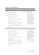
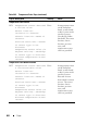
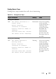
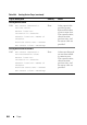
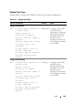

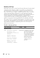
Table Of Contents
- Introduction
- Audience
- What’s New in this Release
- Introduction to the SNMP Reference Guide
- General Content
- Server Administrator Instrumentation MIB
- Server Administrator Remote Access MIB
- Server Administrator Baseboard Management Controller, ASF MIB
- Server Administrator Field Replaceable Unit MIB
- Server Administrator Storage Management MIB
- Server Administrator Change Management MIB
- Dell RAC Out-of-Band MIB
- How This Guide Defines Technical Terms
- SNMP Basic Terminology
- Frequently Used Terms in Variable Names
- Tables
- Reference Guide Content Tables
- Section Organization
- Other Documents You May Need
- Introduction to the Server Administrator SNMP Subagent
- Instrumentation MIB Version Group
- Systems Management Software Group
- Systems Management Software
- Systems Management Software Name
- Systems Management Software Version Number Name
- Systems Management Software Build Number
- Systems Management Software Description Name
- Systems Management Software Supported Protocol
- Systems Management Software Preferred Protocol
- Systems Management Software Update Level Name
- Systems Management Software URL Name
- Systems Management Software Language Name
- Systems Management Software Global Version Name
- Systems Management Software Feature Flags
- Systems Management Software SNMP Agent Feature Flags
- Systems Management Software Manufacturer Name
- Systems Management Software Variable Values
- Systems Management Software
- System State Group
- Chassis Information Group
- Operating System Group
- System Resource Group
- Power Group
- Thermal Group
- User Security Group
- Remote Flash BIOS Group
- Port Group
- Device Group
- Slot Group
- Memory Group
- BIOS Setup Control Group
- Local Response Agent Group
- Cost of Ownership Group
- Remote Access Group
- Cluster Group
- Baseboard Management Controller Group
- Field Replaceable Unit Group
- Storage Management Group
- Storage Management Group
- Storage Management Information Group
- Global Data Group
- Physical Devices Group
- Controller Table
- Channel Table
- Enclosure Table
- Array Disk Table
- Array Disk Enclosure Connection Table
- Array Disk Channel Connection Table
- Fan Table
- Fan Connection Table
- Power Supply Table
- Power Supply Connection Table
- Temperature Probe Table
- Temperature Probe Connection Table
- Enclosure Management Module Table
- Enclosure Management Module Connection Table
- Battery Table
- Battery Connection Table
- Logical Devices Group
- Storage Management Event Group
- Change Management Group
- Dell RAC Out-of-Band Group
- Product Information
- Chassis Status
- DRsGlobalSystemStatus
- DRsGlobalCurrStatus
- DRsIOMCurrStatus
- DRsKVMCurrStatus
- DRsRedCurrStatus
- DRsPowerCurrStatus
- DRsFanCurrStatus
- DRsBladeCurrStatus
- DRsTempCurrStatus
- DRsCMCCurrStatus
- DRsGlobalPrevStatus
- DRsIOMPrevStatus
- DRsKVMPrevStatus
- DRsRedPrevStatus
- DRsPowerPrevStatus
- DRsFanPrevStatus
- DRsBladePrevStatus
- DRsTempPrevStatus
- DRsCMCPrevStatus
- DRsIOMChangeTime
- DRsKVMChangeTime
- DRsRedChangeTime
- DRsPowerChangeTime
- DRsFanChangeTime
- DRsBladeChangeTime
- DRsTempChangeTime
- DRsCMCChangeTime
- Chassis Power
- CMC Power Information
- CMC PSU Information
- Chassis Alerts
- Legacy Alerting
- Traps
- Trap Variables
- Understanding the Trap Description
- Understanding Trap Severity
- Instrumentation Traps
- Miscellaneous Traps
- Temperature Probe Traps
- Cooling Device Traps
- Voltage Probe Traps
- Amperage Probe Traps
- Chassis Intrusion Traps
- Redundancy Unit Traps
- Power Supply Traps
- Memory Device Traps
- Fan Enclosure Traps
- AC Power Cord Traps
- Hardware Log Traps
- Processor Device Status Traps
- Pluggable Device Traps
- Battery Traps
- RAC Traps
- BMC Traps
- Storage Management Alert Reference
- Standard Data Type Definitions
- SNMP Sample Output
- Glossary
- Index
690 Traps
Redundancy Unit Traps
Redundancy means that a system chassis has more than one of certain critical
components. Fans and power supplies, for example, are so important for
preventing damage or disruption of a computer system that a chassis may
have "extra" fans or power supplies installed. Redundancy allows a second or
nth fan to keep the chassis components at a safe temperature when the
primary fan has failed. Redundancy is normal when the intended number of
critical components are operating. Redundancy is degraded when a
component fails but others are still operating. Redundancy is lost when the
number of components functioning falls below the redundancy threshold.
The number of devices required for full redundancy is provided as part of the
trap message when applicable for the redundancy unit and the platform. For
more details on redundancy computation, please refer to the respective
platform documentation.
Table 26-8. Redundancy Unit Traps
Trap ID Description Severity Cause
Redundancy Normal
1304 Redundancy regained
Redundancy unit:
<Redundancy location in
chassis>
Chassis location:
<Name of chassis>
Previous redundancy
state was: <State>
Number of devices
required for full
redundancy: <Number>
Information A redundancy sensor in the
specified system detected
that a "lost" redundancy
device has been reconnected
or replaced; full redundancy
is in effect. The redundancy
unit location, chassis
location, and previous
redundancy state are
provided.