
Reference Guide
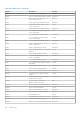
Table Of Contents
- Dell EMC OpenManage SNMP Reference Guide Version 10.1.0.0
- Contents
- Introduction
- What is new in this release
- Supported SNMP Versions
- Managed Object Used in This Document
- Server Administrator Instrumentation MIB
- Server Administrator Baseboard Management Controller, ASF MIB
- Server Administrator Storage Management MIB
- Server Administrator Field Replaceable Unit MIB
- Server Administrator Change Management MIB
- Basic Terminology
- Frequently Used Terms in Variable Names
- Tables
- Section Organization
- Other Documents You May Need
- Introduction to the Server Administrator SNMP Subagent
- System Battery Table
- Amperage Probe Table
- Power Unit Group
- Power Supply Table
- Power Usage Table
- Voltage Probe Table
- System Information Group
- Server Administrator Group
- Instrumentation MIB Version Group
- Systems Management Software Group
- System State Group
- Chassis Information Group
- Operating System Group
- System Resource Group
- Power Group
- Thermal Group
- Remote Flash BIOS Group
- Port Group
- Device Group
- Device Tables
- Pointing Device Table
- Keyboard Device Table
- Processor Device Table
- Processor Device Status Table
- Cache Device Table
- Memory Device Table
- Memory Device Mapped Address Table
- Generic Device Table
- PCI Device Table
- PCI Device Configuration Space Table
- Network Device Table
- Managed System Services Device Table
- SD Card Unit Table
- SD Card Device Table
- Device Group Variable Values
- Device Tables
- Slot Group
- Memory Group
- BIOS Setup Control Group
- Local Response Agent Group
- Cost of Ownership Group
- Cluster Group
- Baseboard Management Controller Group
- Field Replaceable Unit Group
- Storage Management Group
- Storage Management Group
- Storage Management Information Group
- Global Data Group
- Physical Devices Group
- Controller Table
- Channel Table
- Enclosure Table
- Array Disk Table
- Array Disk Enclosure Connection Table
- Array Disk Channel Connection Table
- Fan Table
- Fan Connection Table
- Power Supply Table
- Power Supply Connection Table
- Temperature Probe Table
- Temperature Probe Connection Table
- Enclosure Management Module Table
- Enclosure Management Module Connection Table
- Battery Table
- Battery Connection Table
- Tape Drive Table
- NVME adapter table
- Logical Devices Group
- Storage Management Event Group
- Change Management Group
- SNMP Traps
- Storage Management Alert Reference
- Standard Data Type Definitions
- SNMP Sample Output

Table 1952. Trap Description (continued)
Description Line Item Explanation
Date and time of action: Fri May 30 23:55:44 2003.
Description: <Description
of event>
Specifies the description of the event that occurred, for example:
Description: Chipset Err: Critical Event sensor, front panel
NMI / diagnostic interrupt was asserted.
Device location: <Location
in chassis>
Specifies the location of the device in the specified chassis, for example:
Device location: Mem Card A
Discrete current state:
<State>
Specifies the state of the current sensor, for example:
Discrete current state: Good
Discrete temperature
state: <State>
Specifies the state of the temperature sensor, for example:
Discrete temperature state: Good
Discrete voltage state:
<State>
Specifies the state of the voltage sensor, for example:
Discrete voltage state: Good
Fan sensor value:
<Reading>
Specifies the fan speed in revolutions per minute (RPMs) or On/Off, for example:
Fan sensor value (in RPM): 2600
Fan sensor value: Off
Log type: <Log type>
Specifies the type of hardware log, for example:
Log type: Embedded Server Management (ESM)
Memory device bank
location: <Bank name in
chassis>
Specifies the name of the memory bank in the system that generated the message, for
example:
Memory device bank location: Bank_1
Memory device location:
<Device name in chassis>
Specifies the location of the memory module in the chassis, for example:
Memory device location: DIMM_A
Number of devices required
for full redundancy:
<Number>
Specifies the number of power supply or cooling devices required to achieve full
redundancy, for example:
Number of devices required for full redundancy: 4
Peak value (in Watts):
<Reading>
Specifies the peak value in Watts, for example:
Peak value (in Watts): 125
Possible memory module
event cause: <list of
causes>
Specifies a list of possible causes for the memory module event, for example:
Possible memory module event cause: Single bit warning error
rate exceeded
Single bit error logging disabled
Power Supply type: <type
of power supply>
Specifies the type of power supply, for example:
Power Supply type: VRM
Pre-failure state was:
<State>
Specifies the status of the previous memory message, for example:
Pre-failure state was: Failed
Previous redundancy state
was: <State>
Specifies the status of the previous redundancy message, for example:
Previous redundancy state was: Lost
432 SNMP Traps