
Users Guide

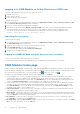


Table Of Contents
- Dell EMC OpenManage Enterprise-Modular Edition Version 1.00.01 for PowerEdge MX7000 Chassis User's Guide
- Overview
- Updating the management module firmware
- Logging in to OME-Modular
- Logging in to OME–Modular as local, Active Directory, or LDAP user
- OME-Modular home page
- Viewing device health
- Setting up chassis
- Initial configuration
- Configuring chassis settings
- Managing chassis
- Chassis groups
- Controlling chassis power
- Backing up chassis
- Restoring chassis
- Exporting chassis profiles
- Managing chassis failover
- Troubleshooting in chassis
- Blinking LEDs
- Interfaces to access OME-Modular
- Viewing chassis hardware
- Viewing chassis alerts
- Viewing chassis hardware logs
- Configuring OME–Modular
- Managing compute sleds
- Managing Storage
- Managing templates
- Managing identity pools
- Ethernet IO Modules
- MX scalable fabric architecture
- SmartFabric Services
- Managing networks
- Managing Fibre Channel IOMs
- Managing firmware
- Monitoring alerts and logs
- Monitoring audit logs
- Troubleshooting
- Storage
- Firmware update is failing
- Storage assignment is failing
- IOM status is downgraded
- IOM health is downgraded
- Drives on compute sled are not visible
- Storage configuration cannot be applied to IOMs
- Drives in OpenManage are not visible
- iDRAC and OpenManage drive information do not match
- The assignment mode of storage sled is unknown
- Storage
- Recommended slot configurations for IOMs
8. Select the Configure all devices to use following catalog check box, select the network share type and click Catalog to
open the Add Firmware Catalog window.
9. Enter a name for the catalog, select the catalog source, and click Finish to save the changes and return to the Chassis
Deployment Wizard.
10. Click Next to view the Proxy tab and configure the proxy settings.
OME–Modular uses the proxy settings to access the Dell EMC website for the latest catalogs. You can also enable the HTTP
proxy settings and proxy authentication.
11. Click Next to view the Group Definition tab.
12. Select Create Group to configure the chassis group settings.
13. Click Next to view the Summary tab.
Configuring chassis settings
You can configure the following settings for a chassis:
● Power
● Network
● Network Services
● Local Access Configuration
● Location
● Quick Deploy
Configuring chassis power
To configure the chassis power settings:
1. Click Devices > Chassis > View Details > Settings > Power.
The Power configuration section is expanded.
2. Select Enable Power Cap to specify the maximum power consumption capacity for the chassis. You can specify the
capacity in Watts, BTU/h, or percentage.
MX7000 chassis supports power sources of 110 volts and 220 volts.
3. In the Redundancy Configuration section, select the required redundancy policy.
Power redundancy policies facilitate management of power consumption and power failure tolerance in the chassis. The
available options are:
● No Redundancy—Powers on the maximum number of devices per the available PSUs. If there are single or multiple
PSU failures, then the system is at risk of degraded performance and other significant power limiting events. The no
redundancy policy distributes power between all the PSUs, and the system limits the power on of devices added to the
chassis to the sum of the capacity of all PSUs.
● Grid Redundancy—Power is distributed by dividing the PSUs into two grids. Grid A consists of PSUs 1, 2, 3, and Grid
B consists of PSUs 4, 5, and 6. To ensure that the maximum power is available to the system, the sum of power supply
capacities on each grid must be equal. The system restricts the power on of devices added to the chassis to the grid with
the largest capacity. If a grid or PSU fails, then the power is distributed among the remaining PSUs with the intent that a
single healthy grid continues to provide power to the system without degraded performance.
● PSU Redundancy—This policy distributes power between all the PSUs. The system restricts the power on of devices
added to the chassis to the sum of the capacity of all the PSUs minus one. If a single PSU fails, then the power is
distributed among the remaining PSUs with the intent that the remaining PSUs continue to provide power to the system
without degraded performance.
Configuring chassis network
You can configure the network settings for chassis that are inserted in a chassis management module.
● LAN/NIC interface
● IPv4
● IPv6
● DNS Information
● Management VLAN
Logging in to OME-Modular
15