
Users Guide


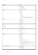


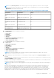
Table Of Contents
- Dell EMC OpenManage Enterprise-Modular Edition for PowerEdge MX7000 Chassis User's Guide
- Contents
- Overview
- Updating firmware for PowerEdge MX solution
- MX7000 Solution Baselines
- Upgrading ethernet switch using DUP
- OME-Modular licenses
- Logging in to OME-Modular
- Logging in to OME–Modular as local, Active Directory, or LDAP user
- Logging in to OME-Modular using OpenID Connect
- OME-Modular home page
- Viewing device health
- Setting up chassis
- Initial configuration
- Configuring chassis settings
- Managing chassis
- Chassis groups
- Controlling chassis power
- Backing up chassis
- Restoring chassis
- Exporting chassis profiles
- Managing chassis failover
- Troubleshooting in chassis
- Blinking LEDs
- Interfaces to access OME-Modular
- Viewing chassis hardware
- Viewing chassis alerts
- Viewing chassis hardware logs
- Configuring OME–Modular
- Viewing current configuration
- Configuring users and user settings
- Configuring login security settings
- Configuring alerts
- Managing compute sleds
- Managing Profiles
- Managing storage
- Managing templates
- Managing identity pools
- Ethernet IO Modules
- MX Scalable Fabric architecture
- SmartFabric Services
- Managing networks
- Managing Fibre Channel IOMs
- Managing firmware
- Monitoring alerts and logs
- Monitoring audit logs
- Use case scenarios
- Troubleshooting
- Storage
- Firmware update is failing
- Storage assignment is failing
- SAS IOM status is downgraded
- SAS IOM health is downgraded
- Drives on compute sled are not visible
- Storage configuration cannot be applied to SAS IOMs
- Drives in OpenManage are not visible
- iDRAC and OpenManage drive information do not match
- The assignment mode of storage sled is unknown
- Unable to access OME-Modular using Chassis Direct
- Troubleshooting lead chassis failure
- Storage
- Recommended slot configurations for IOMs
- Creating validated firmware solution baseline using Dell Repository Manager
- Upgrading networking switch using different OS10 DUP versions
- Upgrading networking switch using CLI

5. Configure the email, SNMP, and system log settings and click Next.
The iDRAC tab is displayed.
6. Select the Configure iDRAC Quick Deploy Settings check box to configure the password to access the iDRAC web
interface and the management IP, and click Next.
You can select the slots to which the iDRAC Quick Deploy settings must be applied.
The Network IOM tab is displayed.
7. Select the Configure I/O Module Quick Deploy Settings check box to configure the password to access the IOM console
and management IPs, and click Next.
The Firmware tab is displayed.
8. Select the Configure all devices to use following catalog check box, select the network share type and, click Catalog to
open the Add Firmware Catalog window.
9. Enter a name for the catalog, select the catalog source, and click Finish to save the changes and return to the Chassis
Deployment Wizard.
10. Click Next to view the Proxy tab and configure the proxy settings.
OME–Modular uses the proxy settings to access the Dell EMC website for the latest catalogs. You can also enable the
HTTPS proxy settings and proxy authentication.
11. Click Next to view the Group Definition tab.
12. Select Create Group to configure the chassis group settings.
13. Click Next to view the Summary tab.
NOTE: After setting the time in the lead chassis, wait for the lead chassis time and the member chassis time to
synchronize before performing any operation. The time configuration can be disruptive.
Configuring chassis settings
You can configure the following settings for a chassis:
● Power
● Network
● Network Services
● Local Access Configuration
● Location
● Quick Deploy
Configure chassis power
To configure the chassis power settings:
1. Click Devices > Chassis > View Details > Settings > Power.
The Power configuration section is expanded.
2. Select Enable Power Cap to specify the maximum power consumption capacity for the chassis. The Power Cap limits the
power consumption of the chassis. When the power cap is reached, the sleds are throttled based on their power priority. You
can specify the capacity in Watts, BTU/h, or percentage. The Power Cap option is displayed only if the Enable Power Cap
check box is selected. The recommended power cap is 0-32767 Watts or 0-100 %. If you change the power cap in BTU/h,
the power cap in W also changes.
MX7000 chassis supports both AC and DC power supply input types.
3. In the Redundancy Configuration section, select the required redundancy policy.
Power redundancy policies facilitate management of power consumption and power failure tolerance in the chassis. The
available options are:
● No Redundancy—This policy distributes the enclosure power load across all PSUs. There are not any specific PSU
population requirements for No Redundancy. The intent of the No Redundancy policy is to have the highest possible
limit for power enablement of devices that are added to the enclosure. If there are single or multiple PSU failures, then
the enclosure limits the performance to operate within the power capabilities of the remaining PSUs.
● Grid Redundancy—This policy distributes the enclosure power load across all PSUs. The six PSUs are organized into
two groups: Grid A consists of PSUs 1, 2, 3, and Grid B consists of PSUs 4, 5, 6. It is recommended that the PSUs
are populated in the following order: 1, 4, 2, 5, 3, 6, where an equal number of PSUs on each grid is optimized for Grid
Redundancy. The grid with the largest PSU capacity determines the limit for power enablement of devices that are added
Logging in to OME-Modular
37