Dell EMC OpenManage Enterprise-Modular Edition for PowerEdge MX7000 Chassis User's Guide July 2021 Rev.
Notes, cautions, and warnings NOTE: A NOTE indicates important information that helps you make better use of your product. CAUTION: A CAUTION indicates either potential damage to hardware or loss of data and tells you how to avoid the problem. WARNING: A WARNING indicates a potential for property damage, personal injury, or death. © 2018 -2021 Dell Inc. or its subsidiaries. All rights reserved. Dell, EMC, and other trademarks are trademarks of Dell Inc. or its subsidiaries.
Revision history Date Document revision Description of changes April 2021 A00 v1.30.00—Updates for new features and enhancements May 2021 A01 v1.30.00—Updates for MX750c platform July 2021 A02 v1.30.10 Support for DC PSU Updates for solution baselines v1.20.00, v1.20.10, v1.30.
Contents Revision history..........................................................................................................................................................................3 Chapter 1: Overview.....................................................................................................................10 Key features....................................................................................................................................................................
Multi-chassis management dashboard...................................................................................................................35 Viewing device health...................................................................................................................................................... 35 Setting up chassis.............................................................................................................................................................
Chapter 6: Managing Profiles...................................................................................................... 72 Creating Profile.................................................................................................................................................................. 72 Viewing Profile...................................................................................................................................................................
Viewing hardware details................................................................................................................................................. 91 Configuring IOM settings................................................................................................................................................. 91 Configuring IOM network settings...........................................................................................................................
Checking compliance.......................................................................................................................................................116 Updating firmware............................................................................................................................................................117 Rolling back firmware............................................................................................................................................
Storage configuration cannot be applied to SAS IOMs....................................................................................136 Drives in OpenManage are not visible.................................................................................................................. 136 iDRAC and OpenManage drive information do not match...............................................................................136 The assignment mode of storage sled is unknown......................................
1 Overview The Dell EMC OpenManage Enterprise Modular (OME-Modular) application runs on the PowerEdge M9002m management module (MM) firmware. OME-Modular facilitates configuration and management of a standalone PowerEdge MX chassis or group of MX chassis using a single Graphical User Interface (GUI). You can use OME-Modular to deploy servers and update firmware.
New in this release This release of OME-Modular 1.30.10 supports: ● DC power supply. ● Compatible BIOS 2.11.2 for MX740c and MX840c. ● Compatible iDRAC 4.40.29.00 for MX750c. ● Compatible OS10 version 10.5.0.9, 10.5.1.9, and 10.5.2.6. ● Revised OS10 update restrictions in section OS10 firmware update matrix . 1.30.00 This release of OME-Modular supports: ● ● ● ● ● ● ● ● ● ● ● ● ● ● ● ● PowerEdge MX750c platform. Group configuration option on the Home page in multichassis environment.
● ● ● ● ● ● Enabling racadm connect to Brocade MXG610s. Performing Hard Reset only on iDRAC instead of whole sled. Setting Name field as the default sort order in device grids. Enhanced alert pop-ups to appear on the upper right corner of the user interface. New SmartFabric Uplink type—Ethernet - No Spanning Tree. Reduction in alert volumes API to replace failed Ethernet switch Autodetection of Scalable Fabric expansion from one to two chassis. 1.10.
● PowerEdge MX9002m Management module Supported web browsers OME–Modular is supported on the following web browsers: ● Google Chrome version 90 ● Google Chrome version 91 ● Mozilla Firefox version 88 ● Mozilla Firefox version 89 ● Microsoft EDGE 90 ● Microsoft EDGE 91 ● Microsoft Internet Explorer 11 ● Safari version 13 ● Safari version 14 For the OME–Modular web interface to load properly in the web browsers, ensure that the Active X or Java script and font download options are enabled.
Accessing documents from Dell support site You can access the required documents in one of the following ways: ● Using the following links: ○ For OpenManage documents—https://www.dell.com/openmanagemanuals ○ For iDRAC and Lifecycle Controller documents—https://www.dell.com/idracmanuals ○ For all Enterprise Systems Management documents—https://www.dell.com/esmmanualsDell.com/ SoftwareSecurityManuals ○ For OpenManage Connections Enterprise Systems Management documents—https://www.dell.
2 Updating firmware for PowerEdge MX solution Component and device firmware for the MX solution are rigorously tested as a validated solution stack or firmware baseline. The details are listed in the table Updating MX7000 components using OME-Modular containing current and previous baselines. When the Dell update packages (DUPs) are available on https://www.dell.com/support , a validated solution stack of the chassis firmware catalog referencing them is published.
Table 2. MX7000—OME-Modular 1.30.10 and previous solution baselines (continued) Validated MX Stack Catalog Version NA 20.07.00 20.10.00 21.04.00 21.07.00 v1.20.00 v1.20.10 v1.30.00 v1.30.10 Dell EMC NA Server BIOS PowerEdge MX750c NA NA 1.1.3 1.2.4 Dell EMC 2.5.4 Server BIOS PowerEdge MX840c 2.8.2 2.9.4** 2.10.2 2.10.2** 2.11.2** 2.11.2** 2.11.2 QLogic 15.05.12 26XX series Fibre Channel adapters 15.05.14 15.15.06 15.20.14 15.20.14 QLogic 15.05.
Table 2. MX7000—OME-Modular 1.30.10 and previous solution baselines (continued) Validated MX Stack Catalog Version NA Componen v1.10.20 t 20.07.00 20.10.00 21.04.00 21.07.00 v1.20.00 v1.20.10 v1.30.00 v1.30.10 Catalog exceptions Channel Adapter Firmware 32G OpenMana ge Enterprise Modular 1.10.20 1.20.00 1.20.10 1.30.00 1.30.10 MX9116n Fabric Switching Engine OS10 10.5.0.5* 10.5.0.7*** 10.5.1.6*** 10.5.2.6 10.5.0.9 10.5.1.7*** 10.5.2.
NOTE: Upgrades from baselines prior to 1.20.00 might need a power cycle (cold boot) of the MX7000 chassis after updating all applicable solution components may be necessary as a last troubleshooting step. For details, see Controlling chassis power. Component update order for individual package method WARNING: Read the update instructions before implementing the update procedure.
i. From the Advance Filters, select Chassis from the Type and enter OpenManage Enterprise Modular in the Component Contains box. ii. Click Select all checkbox and then click Make Compliant. iii. Go to the Monitor > Jobs page to view the job status. iv. Wait for the Chassis updates to complete and then start the Network IOM update. c. Network IOM i. From the Advance Filters, select Network IOM from the Device Type. The list of Network IOM devices is displayed. ii.
2. Click Devices > Compute. A list of the available compute devices in the chassis or chassis group is displayed. 3. In the list header, select the checkbox to select all compute devices on the current page. If there are multiple pages, then go to each page and select the checkbox. 4. After selecting all the compute devices, click Update. 5. In the Device Update wizard, select the individual package and click Browse to select the iDRAC with Lifecycle Controller DUP. 6.
For any firmware update failures on member chassis, restart the firmware update only on the specific target from Lead chassis. Best practices for updating to 1.30.10 While updating the management module to 1.30.10 from an earlier version, ensure that there are no failed template deployment jobs on the Jobs page. If failed deployment jobs exist, then the virtual identities that are reserved for the device for those failed deployments, are added back to the free pool after upgrading to 1.30.10.
Upgrade time for a switch may take between 30 to 120 minutes. Sometimes the upgrade time can be as long as 4.5 hours. To check the upgrade status, you can see OME-M job page or you can log in to the switch and execute show smart-fabric upgrade-status. Upgrading networking OS10 using DUP To upgrade OS10 using DUP, follow these steps: 1. Download the latest DUP file for the switch from https://www.dell.com/support. 2. On the OME-Modular web interface, go to Devices > I/O Modules. 3.
Table 4. OS10 firmware update matrix (continued) To OS10 version 10.4.0 E(R3S P2) 10.4.0E( R4SP2) 10.5.0.1 10.5.0.3 P1 10.5.0.5 10.5.0.9 10.5.1.9 10.5.2.4 10.5.2.6 10.5.1.6/ 10.5.1.7/ 10.5.1.9/ — — — — — — — Yes Yes 10.5.2.4 — — — — — — — — Yes *—Upgrading IOM VLT peers from 10.4.X to 10.5.X version impacts traffic. Regular maintenance window is recommended for this activity. NOTE: Run the X.509v3 certificate upgrade script before upgrading from 10.5.0.1/10.5.0.3P1/10.5.0.5/10.
NOTE: ONIE component firmware is not updated due to the issue of system not booting into ONIE, when GRUB menu is displayed with serial control character. This issue is addressed in 3.35.1.1-15 ONIE firmware version. If ONIE update fails or encounters ONIE booting issue, retry the ONIE component firmware update. Workaround steps for IOM upgrade failure ● When IOMs are upgraded from 10.5.0.7 or 10.5.0.9 to 10.5.2.4 or10.5.2.
3 OME-Modular licenses OME-Modular features are available based on licenses, which are available in XML format. Following are the types of licenses supported: ● Perpetual—Validity is unlimited and is effective until the license is removed or deleted. Perpetual license is bound to the chassis service tag. ● Evaluation—Validity is for a short duration and the timer starts after the license is imported or installed. The timer is a monotonic clock that counts the time that the system is operational.
4 Logging in to OME-Modular You can log in to OME–Modular as a local, Active Directory, or generic Lightweight Directory Access Protocol (LDAP) user. OME–Modular supports a maximum of two Active Directory or LDAP server configurations, each.
After logging in successfully, you can do the following: ● Configure your account. ● Change the password. ● Recover the root password. Integrating directory services in OME-Modular You can use Directory Services to import directory groups from AD or LDAP for use on the web interface. OME-Modular supports integration of the following directory services: 1. Windows Active Directory 2. Windows AD-LDS 3. OpenLDAP 4. PHP LDAP Supported attributes and pre-requisites for LDAP Integration Table 7.
1. On the OME–Modular web interface, click Application Settings > Users > Directory Services > Add > Type of Directory. The Connect to Directory Service window is displayed. 2. From the Type of Directory, select the option, AD or LDAP. The default option is AD. 3. Enter the Directory Name. 4. Select the Domain Controller Lookup. If the Domain Controller Lookup type is DNS and the directory type is AD, enter the domain name and group domain.
Use the DNS domain controller lookup type, if you do not know the details of the domain controllers from which you want to import the group or groups. To use the DNS domain controller, ensure that you have done the following tasks on the Network Settings page: ● Selected the Register with DNS check box. ● Provided the Primary and Alternate DNS server addresses.
The Import Directory window is displayed. 2. From the Directory Source drop-down, select the source from which you want to import the AD or LDAP. 3. Under Available Groups, you can search for directory groups. In the Find a Group text box, enter the first few letters of the group name available in the tested directory. A list of all groups names that begin with the text you entered, is displayed below under the GROUP NAME column. 4. Select a group and click >>.
Table 8. Predefined roles Roles in OME-Modular Roles in OIDC Provider Description CHASSIS_ADMINISTRATOR CA Can perform all tasks on the chassis. COMPUTE_MANAGER CM Can deploy services from a template for compute sleds and perform tasks on the service. STORAGE_MANAGER SM Can perform tasks on storage sleds in the chassis. FABRIC_MANAGER FM Can perform tasks that are related to fabrics. VIEWER VE Has read-only access. To log in to OME-Modular using OpenID Connect: 1.
1. On the OpenID Connect Providers page, select the OIDC provider that you want to enable and click Enable. A message is displayed prompting you to confirm to proceed with enabling the OIDC provider. 2. Click OK to proceed. Disabling OpenID Connect Provider To disable an OpenID Connect Provider: 1. On the OpenID Connect Providers page, select the OIDC provider that you want to enable and click Disable. A message is displayed prompting you to confirm to proceed with disabling the OIDC provider. 2.
● Chassis Subsystems—On the upper right corner of the page, you can view the health of the chassis subsystem components—battery, fan, IOM slot, MM, miscellaneous, power supply, temperature, compute sleds and storage sleds. . When the subsystem status is unhealthy, you can click in the Reason to view the list of fault messages. ● Recent Alerts—On the top center of the page, you can view the most recent alerts for events occurring in the chassis. Click View All, to see all the alerts in the Alerts page.
Page name Fields Jobs ● ● ● ● ● Name Description Enabled/Disabled Last Run Status Created By/Updated By Alert Log ● ● ● ● ● ● Message Category Definition Severity Status Device ○ Model ○ Identifier ○ Type ○ Device Management—MAC Address, Network Address, Device Name, and Discovery Profile Audit Log ● ● ● ● ● ● Category IP Address Message Message Interface Severity User Name Help ● Title ● Content Alert Policy ● Name ● Description ● Enabled/Disabled Users ● ● ● ● ● ● All Devices ● ● ● ● ● ●
Viewing alerts The Alerts section displays the specific types of alerts such as Critical, Warning, and Unknown. You can also view alerts for specific device types such as chassis, compute, networking, and storage. Viewing jobs and activities The Recent Activity section displays a list of recent jobs and activities, and their status. Click All Activity to go to the Jobs page and view detailed information about the jobs.
● Update firmware ● Blink LED ● Refresh inventory NOTE: When you initiate a Leave chassis group request while the inventory refresh is in-progress, an error message is displayed on the All Devices page even if the Leave Chassis Group task is successful. NOTE: When a compute sled is inserted into a chassis, sometimes the message, "No device image found", is displayed. To resolve the issue, refresh the inventory of the compute sled, manually.
5. Configure the email, SNMP, and system log settings and click Next. The iDRAC tab is displayed. 6. Select the Configure iDRAC Quick Deploy Settings check box to configure the password to access the iDRAC web interface and the management IP, and click Next. You can select the slots to which the iDRAC Quick Deploy settings must be applied. The Network IOM tab is displayed. 7.
to the enclosure. If there is a grid or PSU failure, then the enclosure power is distributed among the remaining PSUs with the intent that a single healthy grid continues to provide power to the system without degrading the performance. ● PSU Redundancy—This policy distributes the enclosure power load across all PSUs. There are no specific PSU population requirements for redundant PSUs.
NOTE: Setting Auto Negotiation to false and choosing a network port speed may result in the chassis losing link to the network switch in Top of Rack, or to the neighbor chassis, if running MCM. It is recommended that the Auto Negotiation is set to true for most use cases. Table 9.
isolating the management network is impractical, the other option is to separate OME–Modular and iDRAC traffic to a separate VLAN. OME–Modular and individual iDRAC network interfaces can be configured to use a VLAN. NOTE: Any change in the attribute settings leads to IP drop or unavailability of the OME–Modular web interface for some time. However, the OME–Modular web interface recovers automatically. 8. Click Apply to save the chassis network settings.
OME-Modular command line console features OME-Modular supports the following serial and SSH console features: ● RACADM support ● Integrated connect command connecting to the serial console of servers and I/O modules; also available as racadm connect ● Maximum of four SSH sessions ● Minimum of three and maximum of nine authentication retries for the SSH session OME-Modular command line commands When you connect to the OME-Modular command line, you can enter these commands: Table 10.
● Read-only—Enables read-only access to WiFi and Bluetooth Low Energy (BLE). You cannot write configuration information using quick sync. ● Read-write—Enables writing configuration using quick sync. ● Disabled—Disables reading or writing configuration through quick sync. NOTE: The Quick Sync feature uses a lower radio frequency (RF) power when advertising and increases the RF power after the certificate authentication. The RF range is based on the environment and can vary. 6.
laptop. The processor on the management module emulates a USB network interface and provides a network bridge into the management VLAN. The network is same that QuickSync 2 bridges for OpenManage Mobile Wi-Fi access. When network time protocol setting is not enabled, RCP replacement does not restore system time. The real-time clock on new RCP is then used as system time of lead chassis and the same gets synced to all member chassis which may result in member MSM reboot and MM redundancy loss for some time.
using the public network. If you repeat the action within a short interval, the alert is not displayed. However, the Chassis Direct LED remains amber as the MM suppresses consecutive duplicate alerts. NOTE: While using Internet Explorer to access the phonebook page, a custom certificate larger than 46 Kb results in TLS error. Change the certificate or use a different browser. Configure chassis location To configure the location of the chassis: 1.
● DHCP 6. If the IPv6 Network Type is Static, select the IPv6 Prefix Length and enter the IPv6 Gateway. 7. From the list of slots that is displayed, select the check box next to the slot number to which you want to apply the Quick Deploy settings. 8. In the Network IOM Settings section, enter and confirm the password to log in to the IOM interface. 9. Select IPv4 Enabled to enable the IPv4 network settings and select the IPv4 Network Type. The available options are: ● Static ● DHCP 10.
Viewing chassis overview On the chassis Overview page, you can click View Slot Information to view the compute sled slot details. A graphical representation of the chassis is displayed on the left side. Information about the chassis is displayed below the graphical representation. The information includes FIPS status of the chassis, name, model, service tag, asset tag, express service code, management IP, firmware version, power state, and faceplate power of the chassis.
NOTE: After a chassis power off, the compute SLEDs are polled based on the event from the chassis. Each event from the chassis triggers a health-poll. You may see multiple connection loss events from compute SLEDs. Wiring chassis The automatic uplink detection and network loop prevention features in OME-Modular facilitate connection of multiple chassis with cables. The wiring saves port usage in the data center switches and access each chassis in the network.
Chassis groups You can group many chassis to form a multi-chassis management (MCM) group. An MCM group can have one lead chassis and 19 member chassis. You can use any management module to create an MCM group. The management module that is used for creating the MCM is the leader of the group, by default. The MCM group is of wired type, where the chassis is daisy-chained or wired through a redundant port on the management module.
Creating chassis groups To create a chassis group: 1. On the chassis dashboard, click Overview > Configure > Create Chassis Group. The Create a Group and Configure Lead Chassis wizard is displayed. 2. Enter a name and description for the chassis group you want to create. The group names can contain letters and numbers and must be fewer than 48 characters. However, the group names cannot contain spaces and special characters. 3. Select the onboarding permission type. 4.
● ● ● ● ● ● Alert Destination—Email, SNMP trap, system log Proxy Settings—All settings Security Settings—Login IP range, log on lockout policy Network Services—SNMP, SSH, remote RACADM, web server Local Access Configuration—Chassis power button, quick sync, KVM, LCD, serial access Session Inactivity Timeout Configuration—Session Inactivity Timeout NOTE: Time settings from the lead chassis are synced automatically to all the member chassis in the stack. 5. Click Next to view the summary of the group.
Assigning backup lead In a multi-chassis environment, the lead chassis may sometimes fail temporarily or retire. In such situations, it is necessary to nominate a member chassis in the MCM group as a backup to the lead chassis. The backup lead chassis is promoted as a lead chassis when the existing lead chassis fails or retires. 1. On the MCM dashboard, click Configure > Edit Backup Lead Settings. The Edit Backup Lead Settings window is displayed.
When a backup lead is promoted as the lead chassis, join requests from other member chassis sent to the earlier lead chassis, are not displayed on the MCM dashboard of the new lead. As a result, the particular member chassis cannot send joining requests to other groups in the stack. To unblock the pending requests, run the following API from the member chassis from which the joining requests were sent and resend the requests: URI—/api/ManagementDomainService/Actions/ManagementDomainService.
Delete groups To delete a chassis group: 1. On the chassis dashboard, click Overview > Configure > Delete Group. The Delete Group wizard is displayed. 2. Click Confirm to delete the group. MCM dashboard The MCM dashboard is displayed only when a multi-chassis management (MCM) group is created. You can view the name of MCM group on the left side of the dashboard. Below the group name, you can view the names, IPs, and service tags of the lead and member chassis.
● ● ● ● ● ● Location configuration Slot configuration OME–Modular network settings Users settings Security settings Alert settings You can use the backed-up configuration in other chassis. To create a chassis backup: 1. On the chassis Overview page, click More Actions > Backup. The Backup Chassis window is displayed. 2. In Backup File Location, select the Share Type where you want to store the chassis backup file. The available options are: ● CIFS ● NFS 3.
Managing chassis failover Failover is applicable in dual management module configuration and is the process of transferring the active role to the standby management module. Reboot the active management module and re-initialize the stand-by management module to assume the active role. The failover operation takes up to 10 minutes for completion. OME–Modular is unavailable during this process. You must have the chassis administrator privilege to start a failover.
Table 12. Management module Interfaces (continued) Interface Description and uses the HTTPs channel. The –r option runs the RACADM command over a network. ● Firmware RACADM is accessible by logging in to OME–Modular using SSH or telnet. You can run the firmware RACADM commands without specifying the OME– Modular IP, user name, or password. After you enter the RACADM prompt, you can directly run the commands without the RACADM prefix.
Table 12. Management module Interfaces (continued) Interface Description Chassis Direct The Chassis Direct feature enables you to access management consoles such as iDRAC and management module of devices on the MX7000 chassis. Viewing chassis hardware On the OME–Modular home page, click Hardware to view details of the hardware components that are installed in the chassis. You can also view the chassis hardware details by clicking Devices > Chassis > View Details > Hardware.
Viewing chassis hardware logs The logs of activities performed on the hardware components associated with the chassis are displayed on the OME–Modular Hardware Logs page. The log details that are displayed include severity, message ID, category, timestamp, and description. You can also view the chassis hardware logs by clicking Devices > Chassis > View Details > Hardware Logs.
If you customize the https port, OME-Modular tries to redirect to the new port automatically. However, the redirection may not work owing to security limitations of the browser. In such cases, open a new window or tab of the browser and enter the OME-Modular URL using the customized port. For example, https://10.0.0.1:1443 NOTE: Disabling the OME-Modular web server does not affect the launching of OME-Modular GUI on the phonebook page while using Chassis USB Direct.
Configuring IOM synchronization You can replicate the time and alert destination configuration of the lead chassis in the network and FC IOMs. To configure the time and alert destination: 1. Click Application Settings > Network > IOM Synchronization Configuration. 2. Select the Replicate Time Configuration from Chassis and Replicate Alert Destination Configuration from Chassis check boxes. ● MXG610s supports only three SNMP destination unlike OS10 which supports four SNMP destinations.
Table 13. Ports and protocols that are supported in OME-Modular (continued) Port number Protocol Port type Maximum encryption level Source Direction Destination Usage user to HTTPS. 123 NTP UDP None OME-Modular Out NTP Server Time synchronizati on (if enabled). 137, 138, 139, 445 CIFS UDP/TCP None OME-Modular Out CIFS Share To import firmware catalogs from CIFS share. 161* SNMP UDP None External Application In OpenManage Enterprise Modular For SNMP queries.
Configuring users and user settings In OME–Modular, you can create up to 64 local users and assign them specific roles and privileges. Using the options available under Application Settings > Users, you can add and edit users, import a directory group, and view and terminate active user sessions. NOTE: You can create, delete, enable, or disable users only if you have the security setup privilege. Viewing and editing user accounts 1.
Recovering passwords in single OME-Modular controller 1. From the chassis, remove the single OME–Modular controller. 2. Locate the Jumper, see the board location—P57 RESET PASSWORD, and then insert the Jumper. 3. Reinsert the controller into the chassis. 4. When OME–Modular is available, login with the user name as "root" and password as "calvin". 5. After the root user authentication, change the password for the root user on the Application Settings > Users page. 6.
Table 14.
a. Lockout Fail Count: The number of failed login attempts. Valid values are between 2 and 16. b. Lockout Fail Window: The time within which subsequent failed logins are registered. Valid time is between 2 seconds and 65,535 seconds. c. Lockout Penalty Time: Time for which the logins are restricted. Valid time is between 2 seconds and 65,535 seconds. If the IP is still unavailable, ensure that: ● The network cable is connected.
Configuring email alerts 1. Click Application Settings > Alerts. 2. Click Email Configuration 3. Enter the SMTP Server Network Address. NOTE: The SMTP server network address can have a maximum length of 255 characters. 4. If the server requires authentication, select Enable Authentication. NOTE: If Enable Authentication is selected, you must provide the user name and password to access the SMTP server. 5. Enter SMTP Port Number. 6. If the SMTP server is configured to use SSL, select the SSL option.
5 Managing compute sleds OME–Modular enables you to allocate and manage compute sleds to balance workload demands. You can view the list and details of compute sleds on the Compute page. The details are—health, power state, name, IP address, service tag, and model of the chassis. You can also select a compute sled to view the graphical representation and summary of the compute sled, on the right side of the Compute page. Select a compute sled from the list to view a summary of the sled on the right side.
Below the Recent Alerts is the Recent Activity section, which displays the list of recent activities that are associated with the compute. The status and timestamp of completion of the activities are also displayed. Click View All to view the list of all activities in the Jobs page. NOTE: The time that is displayed is based on the time zone of the system from where OME-Modular is accessed. A graphical representation of the remote console is displayed on the right-side of the page.
● Turn-on or turn off LEDs using Blink LED. The available options are: ○ 1 Minute ○ 10 Minutes ○ 30 Minutes ○ 1 Hour ○ Indefinitely Configuring compute settings You can configure the following compute settings: ● Network ● Management Configuring compute network settings Once Quick Deploy settings are applied to a compute sled, the settings may be reported after some time due to data refresh in OME-Modular. To configure the compute network settings: 1.
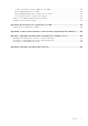
Figure 1. Compute sled replacement—flowchart Table 15. Compute sled replacement - Behavior of OME-Modular and LCD panel OME-Modular behavior LCD behavior Case 1 Enables users to clear all mappings to the compute sled. Enables users to clear all mappings to the compute sled. Case 2 Enables users to clear or retain all mappings to the compute sled. Enables users to clear or retain all mappings to the compute sled.
Viewing compute hardware logs The logs of activities performed on the hardware components associated with the compute sled are displayed on the compute Hardware Logs page. The log details that are displayed include severity, message ID, category, timestamp, and description. To view the hardware logs, click Devices > Compute > View Details > Hardware Logs.
6 Managing Profiles OME–Modular allows you to create server profiles and apply them to compute sled or slot.
● View Profile—You can view Boot to Network ISO, iDRAC Management IP, Target Attribute, and Virtual Identities information that is related to the profile. ● View Network—You can view Bandwidth and VLANs information that is related to the profile. On the Profiles page, select a profile and click View and select View Profile. The View Profile wizard is displayed. Editing Profile You can Rename and Edit the profile to change the existing settings.
1. On the Profiles page, select a profile and click Assign. The Deploy Profile wizard is displayed. 2. On the Details tab, verify the details and click Next. The Target tab is displayed. 3. Select Attach to Slots or Deploy to Devices and click Select Slots. The Select Device wizard is displayed. 4. Select the device from All Devices, click Finish and then click Next. The Boot to Network ISO tab is displayed. 5. Select Boot to Network ISO and enter the following file share information and click Next.
Redeploying Profile You can redeploy profiles which are in the deployed profile state. When Quick Deploy and Profile settings are enabled for the slot, a deployment and configuration job is created every time that a sled inserted. If the profile contains RAID attributes, the RAID settings are reconfigured. Disable Quick Deploy when RAID configuration exists in the profile. To redeploy the profile: 1. On the Profiles page, select a deployed profile that you want to redeploy and click Redeploy.
7 Managing storage This chapter describes the Storage and IOM features of OME–Modular. It also provides details about performing various storage-related tasks. The SAS IOMs manage the storage enclosures. SAS IOMs facilitate communication between storage and compute sled and also help in assigning the storage to the compute sleds.
1. From the Devices drop-down menu, select Storage. 2. Select the storage sled. 3. Click Blink LED and click Turn On. To turn off the LED blinking: 1. From the Devices drop-down menu, select Storage. 2. Select the storage sled. 3. Click Blink LED and click Turn Off. You can pull out the storage sled trays from the chassis to access the storage sled drives.
Current Mode—Indicates if the hard drive is assigned to an enclosure or to a single compute node slot. ● Enclosure-Assigned—In this mode, you can assign an entire storage sled to one or more compute node slot. NOTE: You cannot assign storage when a redundant SAS IOM setup is temporarily degraded to nonredundant state. NOTE: The storage enclosure is assigned to the slots of the compute slots and not to the sled itself.
To assign an enclosure: 1. From the Devices drop-down list, select Storage. 2. Select the storage sled from the list of the storage devices. 3. Click View Details. The storage Overview page is displayed. 4. Click Hardware and select Enclosure-Assigned. A warning message about loss of data while selecting this mode is displayed. 5. Select I understand that reseting this assignment could result in data loss and click Ok. 6. Select the compute sled slots and click Assign.
○ Reboot server immediately—Select this check box to send the update and reboot the server immediately. You can select the reboot options from the drop-down, the available options are: ■ Graceful Reboot with Forced Shutdown ■ Graceful Reboot without Forced Shutdown ■ Power Cycle ○ Stage for next server reboot—Select this check box to send the update to the server. However, the update is installed only the next time the server is rebooted. a.
● ● ● ● ● ● ○ Power Cycle—The Power Cycle option initiates a warm reboot of the IOM. In this instance, the power is not removed from the IOM and the core systems of the IOM reboot. ○ System Reseat—The System Reseat option removes the IOM virtually. In this instance, the power is removed from the IOM and the IOM reboots. NOTE: After the power reseat of the SAS IOM, the IOM turns on within a minute.
8 Managing templates OME–Modular allows you to configure servers based on templates. A server template is a consolidation of configuration parameters that are extracted from a server and used for replicating the configuration to multiple servers quickly. A server profile is a combination of template and identity settings that are applied to a specific or multiple servers, or saved for later use. You must have the template management privilege to create templates.
Creating templates You can create templates in the following ways: ● Clone from an existing server—Reference Device ● Import from an external source—Import from File To create a template from a reference device: 1. On the Templates page, click Create Template and select From Reference Device. The Create Template wizard is displayed. 2. Enter the name and description for the template and click Next. The Reference Device tab is displayed. 3.
Cloning templates To create a copy of a template: On the Templates page, select the template of which you want to create a copy, and click Clone. Exporting templates You can export a template to a network share or a local drive on your system. To export a template: On the Templates page, select the template that you want to export and click Export. A message is displayed to confirm the export action. The template is exported in .xml format to a local drive on your system or a network share.
4. Select or clear the Propagate VLAN Settings. Selecting this option will propagate any changes to VLAN settings to sleds which were previously targeted by this template. Deploying templates You can deploy templates from the Deploy Template and Template Details pages. After a template is deployed on one or more servers along with VLAN configurations, if you make a mistake or decide to change the existing VLAN configurations on the Fabric Manager, perform the deployment workflow again.
If the template has identity attributes, but is not associated with a virtual identity pool, an error message is displayed. Else, the Deploy Template wizard is displayed. 2. Select the target slot or device on which you want to deploy the template, enter the ISO path and location details, configure the iDRAC management IP settings, select the Do not forcefully reboot the host OS if the graceful reboot fails option if the reboot is required, and schedule the deployment.
9 Managing identity pools Identity pools are used in template-based deployment of servers. They facilitate virtualization of network identities that are required for accessing systems using Ethernet, iSCSI, FCoE, or Fibre Channel (FC). You can enter the information that is required for managing the I/O identities. The identities, in turn, are managed by chassis management applications such as OME–Modular.
The Identity Pools page is displayed with the list of available identity pools and their key attributes. 2. Click Create. The Create Identity Pool wizard is displayed. 3. Enter a name and description for the identity pool and click Next. The Ethernet tab is displayed. 4. Select Include Ethernet virtual MAC Addresses to enter the Starting virtual MAC Address, select the Number of Virtual MAC Identities you want, and click Next.
○ ○ ○ ○ Slot Name Management IP NIC Identifier You must have the template management privilege to manage identity pools. You can filter and view the usage details by: ● ● ● ● Ethernet iSCSI FCoE FC Editing identity pools You can modify the number of entries in the identity pool. However, you cannot reduce the size of the identities that are already assigned or reserved.
10 Ethernet IO Modules The MX7000 supports the following Ethernet I/O Modules (IOMs): ● Managed Ethernet switches: ○ MX9116n Fabric Switching Engine ○ MX5108n Ethernet Switch ● Unmanaged devices: ○ MX7116n Fabric Expander Module ○ PowerEdge MX 25 Gb Ethernet Pass-Through Module ○ PowerEdge MX 10GBASE-T Ethernet Pass-Through Module Ethernet IOMs are supported in Fabrics A and B. For details about the supported IOM slots, see Supported slot configurations for IOMs.
NOTE: When a switch changes between Full Switch and Fabric modes, it reboots. NOTE: If the compute sled and fabric IOM mismatch, the health status of the compute or IOM is displayed as "Warning" in the chassis subsystem health. However, the health status is not displayed in the chassis graphical representation on the Chassis page, I/O Modules, and Compute pages.
To configure the networking settings: 1. Click All Devices > I/O Modules > View Details > Settings > Network or Devices > I/O Modules > View Details > Settings > Network. 2. In the IPv4 Settings section, select Enable IPv4. 3. Enter the IP Address, Subnet Mask, and Gateway for the management port. The IP Address, Subnet Mask, and Gateway options are enabled only if the Enable DHCP check box is cleared.
1. Click All Devices > I/O Modules > View Details > Settings > Monitoring or Devices > I/O Modules > View Details > Settings > Monitoring. 2. Select the Enable SNMP checkbox to enable of disable the SNMP. 3. From SNMP Version, select SNMP v1 or SNMP v2. 4. Enter the Read Community String to fetch requests from the OME Modular daemon directed at the IOM. 5. Click Apply to save the monitoring settings or click Discard to clear the changes and go back to the previous settings.
Configuring admin status You can switch the admin status for all ports, which is enabled by default. You can set the administrative status to enabled or disabled. To switch the admin status: Select the port and click Toggle Admin State. The Toggle Admin State window is displayed. Configuring Maximum Transmission Unit You can configure the Maximum Transmission Unit (MTU) for full-switch and fabric mode IOMs. To configure MTU: 1. Click Devices > I/O Modules > View Details > Hardware > Port Information. 2.
To configure FEC: 1. On the Port Information page, expand the physical port group, and select the Ethernet port . 2. Click Configure FEC. The Configure Forward Error Correction window is displayed. 3. Select the FEC Type. The available options are: ● Auto—Applies FEC based on the cable or optic connected ● Off—Disables FEC ● CL74-FC— Configures CL74-RS FEC and supports 25G and 50G ● CL91-RS—Configures CL91-RS FEC and supports 100G ● CL108-RS—Configures CL108-RS FEC and supports 25G and 50G 4.
11 MX Scalable Fabric architecture The scalable fabric architecture ties multiple MX7000 chassis into a single network domain to behave like a single logical chassis from a networking perspective.
Recommended physical topology The recommended minimum design for a scalable fabric is two chassis with Fabric A populated with redundant IOMs. Ideally, the two chassis are located in separate racks on separate power circuits to provide the highest redundancy. Additional chassis only have FEMs and the appear as the image below. Table 16.
Restrictions and guidelines The following restrictions and guidelines are applicable when building a scalable fabric: ● Mixing switch types in the same fabric is not supported. For example: MX9116n in slot A1 and MX5108n in slot A2 ● Mixing switch types across fabrics is supported. For example: MX9116n in slots A1& A2 and MX5108n in slots B1 & B2 ● All FSE and FEM IOMs in a scalable fabric must be in the same OME–Modular MCM group.
12 SmartFabric Services SmartFabric Services is a capability of Dell EMC Networking OS10 Enterprise Edition running on Ethernet switches that are designed for the PowerEdge MX platform. A SmartFabric is a logical entity containing a collection of physical resources such as servers and switches and logical resources —networks, templates, and uplinks.
• • • • • • NIC teaming restrictions OS10 CLI commands available in SmartFabric mode Fabrics Overview Viewing topology details Viewing Multicast VLANs VLANs for SmartFabric and FCoE Guidelines for operating in SmartFabric mode The guidelines and restrictions while operating in SmartFabric mode are as follows: ● When operating with multiple chassis, ensure that the switches in A1/A2 or B1/B2 in one chassis are interconnected only with other A1/A2 or B1/B2 switches respectively.
In SmartFabric mode, ports 9 and 10 are automatically configured in a VLT at 40GbE speed. For port 10, use a cable or optic that supports 40GbE and not 100GbE. 2 x MX9116n Fabric Switching Engines in the same chassis Use this placement in environments with a single chassis. The switches must be placed in either slots A1/A2 or slots B1/B2. A SmartFabric cannot include a switch in Fab A and a switch in Fab B.
NOTE: You cannot select the ports, and the connection topology is enforced by SmartFabric Services. NOTE: VLT is supported only on Ethernet and not on FCoE. Physically separate uplinks for LAN and FCoE traffic are required for MX5108n and MX9116n switches. Upstream network switch requirements It is recommended, but not required, that PowerEdge MX switches are connected to a pair of redundant upstream switches.
2. If NPAR IS in use, only Switch Independent teaming methods are supported. Switch-Dependent teaming is NOT supported. The following restrictions are applicable to Switch Dependent (LACP) teaming: 1. The IDRAC shared LOM feature can only be used if “Failover” option on IDRAC is enabled. 2. If the host operating system is Windows, the LACP timer MUST be set to “slow” (also referred to as “normal”).
Adding SmartFabric To add a fabric: 1. Click Devices > Fabric . The Fabric page is displayed. 2. Click Add Fabric. The Create Fabric window is displayed. 3. Enter Name and Description, and then click Next. 4. Select the Design Type from the drop-down.
● FC Gateway—You can pick one or more ports from the same IOM and associate a single network of FCoE type. This type of uplink is for connectivity to a SAN switch. For single Fabric, you can have two FC gateway uplinks one from each IOM. Both IOMs must have different network that is, different FCoE VLANs. For a given fabric, you can have at least one uplink of type FC (either of FCoE, FCDirectAttach, FC Gateway).
Deleting uplinks To delete an uplink: 1. From the Devices drop down, select Fabric. The Fabric page is displayed. 2. In the fabrics table, select any fabric and click View Details. 3. In the uplinks table, select the uplink to be deleted. 4. Click Delete. Click Yes to confirm the deletion. Deleting fabric To delete an existing fabric: 1. From the Devices drop-down, select Fabric. The Fabric page is displayed. 2. From the fabrics table, select the fabric that you want to delete. 3. Click Delete.
If you are implementing Fibre Channel configurations, you can also configure VLANs for FCoE. The storage arrays have two separate controllers that create two paths—SAN path A and SAN path B. These paths are connected to MX9116n FSE. For storage traffic to be redundant, two separate VLANs are created for that traffic. The following table lists examples of VLAN attributes for FCoE traffic: Table 18.
Table 19. Maximum number of VLANs recommended in SmartFabric mode (continued) OS10 Version Parameter Value Maximum VLANs per uplink 1536 Maximum VLANs per server port 512 Maximum VLANs per fabric 512 Maximum VLANs per uplink 512 Maximum VLANs per server port 256 Maximum VLANs per fabric 256 Maximum VLANs per uplink 256 Maximum VLANs per server port 64 10.4.0.R3S Maximum VLANs per fabric 128 10.4.0.R4S Maximum VLANs per uplink 128 Maximum VLANs per server port 32 10.5.1.6-10.5.1.
13 Managing networks You can configure logical networks that represent your environment, for the tagged and untagged VLANs. These logical networks are used to provision the appropriate VLANs on the associated switch port for the physical server NIC port. NOTE: VLANs are only assigned to servers connected to switches in SmartFabric mode. For servers connected to switches in Full Switch mode, the VLAN information is ignored. In tagged networks, a port handles multiple VLANs.
Table 22. Network traffic types - QoS settings (continued) Network Traffic Type Description QoS Setting Storage - FCoE Used for FCoE VLANs 5 Storage - Data Replication Used for VLANssupporting storage data replication such as for VMware VSAN 5 VM Migration Used for VLANs supporting vMotion and similar technologies 5 VMWare FT Logging Used for VLANs supporting VMware Fault Tolerance 5 Defining networks To configure a logical network: 1. Click Configuration > VLANs. The VLANs page is displayed.
Importing VLANs To import VLANs: 1. On the VLANs page, select the required network and click Import, and select Import from File. The Import from File window is displayed. 2. Click Select a File to browse and import the file from the destination. The supported file types are .csv and .json. 3. Click Finish to import the VLANs. Deleting VLANs To delete a VLAN: On the Networks page, select the VLAN and click Delete.
14 Managing Fibre Channel IOMs The MXG610s Fibre Channel (FC) switch is designed for mission critical applications accessing data on external storage. It is optimized for flash storage and virtualized server environments. The FC switch enables organizations to dynamically scale connectivity and bandwidth Ports-on-Demand (PoD). It enhances operations with consolidated management and simple server and storage connectivity. OME–Modular makes the management of the MXG610s simple.
15 Managing firmware The firmware feature in OME–Modular helps you to update the firmware of all the components in the chassis. The components include compute sleds, ethernet IOMs, storage IOMs, and SAS IOMs. The firmware updates can be sources from the Dell website or a custom repository setup using Repository Manager. You must have the chassis administrator role and the device update privilege for the chassis to update the firmware on the chassis.
Managing catalogs The catalog management feature in OME–Modular lets you choose the list of DUPs to use with baselines to determine firmware compliance. The catalogs can be sourced from the following locations: ● Newest validated stacks of chassis firmware on Dell.com—Component and device firmware for the MX solution are rigorously tested together as an end to end validated solution stack or firmware baseline. The validated stack is the same as latest solution baseline.
The available options are: ● Newest validated stacks of chassis firmware on Dell.com—The versions of firmware in this catalog have been tested together as part of the latest OME - Modular firmware release. NOTE: When the validated stacks option is selected, the details will be available only after the data is persisted to the database. ● Latest component firmware versions on Dell.com— This catalog is updated on the second and fourth Friday of every month with new firmware.
Deleting catalogs You can only delete catalogs that are not associated with a baseline. If you attempt deleting a catalog that is associated with a baseline, an error message is displayed. To delete a catalog: On the Catalog Management page, select the catalog that you want to delete and click Delete. Creating baselines To create a firmware baseline: 1. Click Configuration > Firmware Compliance > Create Baseline . The Create Firmware Baseline window is displayed. 2.
NOTE: Firmware downgrade for network IOMs is not supported from OME-M using DUP. For more information, see the OpenManage Enterprise-Modular Edition for PowerEdge MX7000 Chassis User's Guide or OS10 Enterprise Edition User Guide. The compliance status can be of types: ● Unknown—The firmware version for the component or device is not available in the catalog.
NOTE: During firmware update, when the active MM reboots and the standby MM is active, some messages on the Execution Details page for the firmware update are not displayed. The messages are not displayed owing to synchronization issues. NOTE: During the OME–Modular firmware update, multiple users can upload the OME–Modular DUP using any interface. However, a warning message may be displayed after the firmware update job is initiated.
Rolling back firmware If you are not convinced with the firmware update of a device or component, you can roll back the update to the version before the update. The rollback option is enabled only if OME–Modular can access the firmware package of the previous version. The following methods can be used to enable the access: ● A Device that has the rollback version (or N-1 version) that matches the previous version. Not all devices support a rollback or N-1 version.
16 Monitoring alerts and logs You can view and manage the alerts that are generated in the management system environment. You can filter alerts and perform the appropriate actions. Every chassis in the MCM group receives Fabric alerts, irrespective of whether the MX5108N or MX9116N IOMs present in the chassis to accommodate new MX5108N or MX9116N IOMs in the chassis. To view the alerts page, from the menu bar, click Alerts.
Acknowledging alert logs You can acknowledge alert logs that are not already acknowledged. Acknowledging an alert prevents storing the same event in the system. For example, if a device is noisy and is generating the same event multiple times, you can ignore further recording of the alert by acknowledging the events that are received from the device. And, no events of the same type are recorded further.
● ● ● ● Edit alert policies Enable alert policies Disable alert policies Delete alert policies OME–Modular also offers pre-defined alert policies for monitoring the systems, after the alert destinations are configured. Creating alert policies To receive Fabrics or Uplink related alerts from the source Fabric Manager, on the configured external destinations, select Network IOM or All Devices as Groups instead of Devices while configuring the alert policy.
Enabling alert policies You can enable alert policies that are disabled. You can enable more than one alert policy at a time. To enable alert policies: On the Alert Policies page, select the alerts that you want to enable and click Enable. A confirmation message is displayed. Editing alert policies You can edit alert policies. To edit alert policies: On the Alert Policies page, select the alerts that you want to edit and click Edit. A confirmation message is displayed.
Filtering alert definitions To filter alert definitions: 1. On OME–Modular web interface, navigate to Alerts > Alert Definitions. 2. Click Advanced Filters. 3. Select or update the following based on your requirement: ● ● ● ● Message Contains—To view alerts containing a specific word in the message column. Message—To view alerts containing a specific numeric or alphanumeric character. Category and Subcategory—To view alerts of specific category. Severity—To view all alerts with specific severity level.
17 Monitoring audit logs The audit log feature in OME–Modular enables you to monitor log entries related to: ● Log in attempts ● Appliance setup ● Chassis configuration change using RESTful API ● Change in alert filter configuration On the Audit Log page, you can perform the following tasks: ● Sort the audit logs using the Advanced Filter. ● Export all the audit logs in .csv format to a network share or local drive on your system.
Monitoring jobs You can view the status of and details of jobs that are initiated in the chassis and its subcomponents, on the Jobs page. The jobs include firmware update and inventory refresh for devices. To view the Jobs page, from the menu bar, click Monitor > Jobs. You can perform the following tasks on the Jobs page: ● ● ● ● ● ● ● Filter jobs using Advanced Filter View a summary of the job.
○ ○ ○ ○ ○ ○ ○ ○ ○ ○ ○ ○ ○ ○ ○ ○ ○ ○ MCM Assign Backup Lead MCM Group MCM OffBoarding MCM OnBoarding MCM Promote Backup Lead MCM Reassign Backup Lead MCM Security Settings Sync Task MCM Retire Lead MCM Settings Propagation MCM Unassign Backup Lead Profile Update Quick Deploy Restore Settings Update Software Rollback SyncronizeDate Task Time Settings Update NOTE: The option, Data Synchronization, is meant for troubleshooting and available only in the RESTful API interface.
A summary of the job is displayed on the right side of the Jobs page. 2. Click View Details. The Job Details page is displayed. The details including name, description, execution details, and the details of the system on which the job was run, are displayed. On Job Details page, you can perform the following tasks: ● Restart the job ● Export details of the job in a .
To disable jobs: On the Jobs page, select the enabled jobs that you want to disable and click Disable. A confirmation message is displayed and the state of the selected jobs changes to "Disabled". Deleting jobs To delete jobs: On the Jobs page, select the jobs that you want to delete and click Delete. A message is displayed prompting you to confirm the operation.
18 Use case scenarios Use case scenarios for the backup lead chassis feature are described in this chapter. Topics: • • Assigning backup to the MCM Lead Scenarios when backup lead can take over as lead chassis Assigning backup to the MCM Lead The backup lead chassis feature facilitates management of systems in the chassis group when the existing lead chassis fails.
Initially, the backup health status is displayed as "Critical" while the configuration data is being synchronized before changing to "OK". Wait for the backup health to transition to "OK" before proceeding. If the backup health continues to report "Critical" or "Warning" even after 30 minutes of the assign task, it is an indication that there are persistent communication issues. Unassign the backup and repeat the Step 5 to choose another member as the new backup.
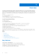
Figure 2. Network and power outage—flowchart The alert, CDEV4007, is related to network or power issues that can be classified as: ● Intermittent/recoverable issues—Momentary power or network outages. The administrator can identify these types of failures and perform recovery actions locally or remotely. Do not promote the backup lead. Allow the lead chassis to recover connectivity automatically or the administrator fixes the power or network issues.
1. Before running the "promote" task on the backup lead chassis: a. The "promote" task is a disruptive operation and must be used only when there are no means to recover the inaccessible lead chassis. In partial failures of the lead chassis, for example; if only the management modules are nonresponsive, but the computes are working, running the promote task disrupts workloads that are still running on the lead chassis computes.
URI: /api/ApplicationService/Actions/ApplicationService.ResetApplication Method: POST Payload: {"ResetType": "RESET_ALL", "ForceReset": true} d. Relocate the working components of the old lead to other chassis in the group: i. Relocate network switches from the old lead to the new lead or member chassis in the group to restore the health of the fabrics. ii. Relocate computes from the old lead to the new lead or member chassis in the group.
19 Troubleshooting This section describes the tasks for troubleshooting and resolving issues using the OME–Modular user interface.
2. A non-SAS IOM is detected. 3. An inconsistency is detected in the subcomponent firmware. Drives on compute sled are not visible 1. If the compute sled is configured with a PERC controller and the drives have been reseated or moved, they are rediscovered as "Foreign". 2. If the drives are removed from the storage sled, they cannot be discovered. 3. If a storage sled is replaced, the storage configuration of the earlier sled cannot be applied to the replaced sled.
3. Connect the stacking cable and add the stand-alone member to the same or different chassis group.
A Recommended slot configurations for IOMs The table below contains the recommended IOM slot configurations. Table 25.
Table 26.
B Creating validated firmware solution baseline using Dell Repository Manager Dell Repository Manager (DRM) allows you to create a repository and access catalogs from OME-M which can be later imported using CIFS, NFS, or HTTPS. Adding repository for the baseline After installing and launching the DRM, add a repository for the baseline that has to be standardized.
4. Select Network Path, enter corresponding network details. 5. Click Test now to verify the test connection. 6. Click Finish.
C Upgrading networking switch using different OS10 DUP versions The following sections provide you the information to upgrade OS10 using different DUP versions. NOTE: When you upgrade VLT peers from 10.4.0E (R3S or R4S) to 10.5.0.1 or later during the maintenance window, it may impact traffic during the upgrade. NOTE: The DUP update procedure is recommended to upgrade OS10 on the MX9116n and MX5108n. Topics: • • • Upgrading networking switch to 10.5.0.7 or 10.5.0.
3. Go to the SmartFabric Services CLI prompt using the command: python /opt/dell/os10/bin/rest-service/tool/dnv_cli.py 4. Get the main IOM service tag using below command: show cluster Prerequisites for upgrading from 10.5.0.5 ● When updating, ensure to update the IOMs in groups no larger than four per upgrade job. ● If there are two switches in a full-switch mode VLT, each switch should be part of different upgrade batch for redundancy. ● If there are two switches in a SmartFabric, select only one switch.
D Upgrading networking switch using CLI NOTE: Upgrade the MX9116n and MX5108n switches to 10.5.1.9 or 10.5.2.6 only if the switches are running 10.5.0.9 or certificate installed 10.5.0.7. For more information, see OS10 firmware update matrix. NOTE: Upgrade the MX9116n and MX5108n switches to 10.5.1.X only if the switches are running 10.5.0.7 or later. While updating, ensure that the IOMs in the group are not more than six per upgrade job. NOTE: To upgrade the networking switch from 10.4.
Table 30. Command description Command Description OS10# show image status View the current software download status. e. Install the 10.5.0.5 software image in EXEC mode. Table 31. Command description Command Description OS10# image install image-url Install the software image. Example: OS10# image install image://filename.bin f. (Optional) View the status of the current software install in EXEC mode. Table 32.
NOTE: During the image upgrade process in a VLT setup, if the VLT peers are running different software versions, do not change the configuration in any VLT peer. Ensure that both the nodes are upgraded to the same version before you change the configuration.