
Deployment Guide
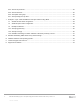
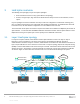
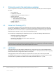
Table Of Contents
- 1 Introduction
- 2 Hardware overview
- 3 Leaf-spine overview
- 4 Protocols used in the leaf-spine examples
- 5 Layer 3 configuration planning
- 6 Example 1: Layer 3 with Dell EMC leaf and spine switches using OSPF
- 7 Example 2: Layer 3 with Dell EMC leaf and spine switches using eBGP
- A Dell EMC Networking ONIE switch factory default settings
- B Validated hardware and operating systems
- C Technical support and resources
- D Support and Feedback
8 Dell EMC Networking Layer 3 Leaf-Spine Deployment and Best Practices with OS10 | Version 1.0
Internal Use - Confidential
3 Leaf-spine overview
The following concepts apply to layer 3 leaf-spine topologies:
Each leaf switch connects to every spine switch in the topology.
Servers, storage arrays, edge routers and similar devices always connect to leaf switches, never to
spines.
Layer 3 topologies use two leaf switches at the top of each rack configured as a Virtual Link Trunking (VLT)
pair. VLT allows all connections to be active while also providing fault tolerance. As administrators add racks
to the data center, two leaf switches configured for VLT are added to each new rack.
The total number of leaf-spine connections is equal to the number of leaf switches multiplied by the number of
spine switches. To increase fabric bandwidth additional connections between leaf and spine switches can be
implemented as long as the spine layer has the capacity for the additional connections.
3.1 Layer 3 leaf-spine topology
In a layer 3 leaf-spine network, traffic between leaf and spine switches is routed. The layer 3 / layer 2
boundary is at the leaf switches. This means at the leaf layer and below (leaf switches and hosts),
communication is achieved at layer 2. However, communication at and above the leaf switches is achieved at
layer 3. Spine switches are never connected to each other in a layer 3 topology. Equal cost multi-path routing
(ECMP) is used to load balance traffic across the layer 3 network. Connections within racks from hosts to leaf
switches are layer 2. Connections to external networks are made from a pair of edge or border leaf switches
as shown in Figure 6. Connections from the data center core can also be made directly to the spines.
Rack 2Rack 1
Leaf 4
Leaf 3
VLTi
Leaf 2
Leaf 1
VLTi
Rack n
Edge Leaf
Edge Leaf
VLTi
Spine 1 Spine 2Spine 1 Spine 2
L3 Connection
L3
L2
L3
L2
Host
VLT
Host
VLT
ECMP
L2 Connection
Host
VLT
External
Network
Layer 3 leaf-spine network