
Deployment Guide
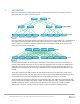
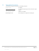
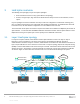
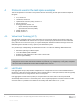
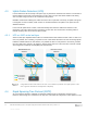
Table Of Contents
- 1 Introduction
- 2 Hardware overview
- 3 Leaf-spine overview
- 4 Protocols used in the leaf-spine examples
- 5 Layer 3 configuration planning
- 6 Example 1: Layer 3 with Dell EMC leaf and spine switches using OSPF
- 7 Example 2: Layer 3 with Dell EMC leaf and spine switches using eBGP
- A Dell EMC Networking ONIE switch factory default settings
- B Validated hardware and operating systems
- C Technical support and resources
- D Support and Feedback
5 Dell EMC Networking Layer 3 Leaf-Spine Deployment and Best Practices with OS10 | Version 1.0
Internal Use - Confidential
1 Introduction
Data center networks have traditionally been built in a three-layer hierarchical tree consisting of access,
aggregation and core layers as shown in Figure 1.
Spine 1
Aggregation
Access
Core
Hierarchical networking model
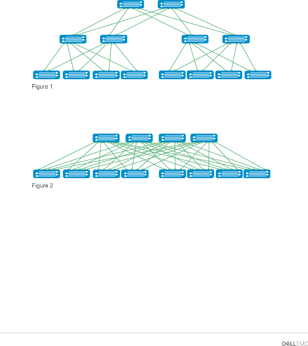
Due to increasing east-west traffic within the data center (server-server, server-storage, etc.), an alternative to
the traditional access-aggregation-core network model is becoming more widely used. This architecture,
shown in Figure 2, is known as a leaf-spine network and is a non-blocking network where all devices are
exactly the same number of hops away.
Spine
Leaf
Leaf-spine architecture
In a leaf-spine architecture, the access layer is referred to as the leaf layer. Servers and storage devices
connect to leaf switches at this layer. At the next level, the aggregation and core layers are collapsed into a
single spine layer. Every leaf switch connects to every spine switch to ensure that all leaf switches are no
more than one hop away from one another. This minimizes latency and the likelihood of bottlenecks in the
network.
A leaf-spine architecture is highly scalable. As administrators add racks to the data center, a pair of leaf
switches are added to each new rack. Spine switches may be added as bandwidth requirements increase. If
the initial spine layer is exhausted an additional layer can be deployed creating a 3-tier model.
The interconnections between leaf and spine are dynamically routed. This deployment guide provides step-
by-step configuration examples using eBGP or OSPF to provide dynamic routing. It includes examples using
Dell EMC Networking switches at both the leaf and spine layers. The objective is to enable a network
administrator or engineer to deploy a layer 3 leaf-spine architecture using the examples provided.