
Deployment Guide
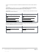
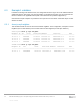
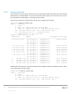
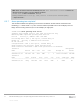
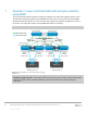
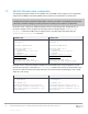
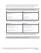
Table Of Contents
- 1 Introduction
- 2 Hardware overview
- 3 Leaf-spine overview
- 4 Protocols used in the leaf-spine examples
- 5 Layer 3 configuration planning
- 6 Example 1: Layer 3 with Dell EMC leaf and spine switches using OSPF
- 7 Example 2: Layer 3 with Dell EMC leaf and spine switches using eBGP
- A Dell EMC Networking ONIE switch factory default settings
- B Validated hardware and operating systems
- C Technical support and resources
- D Support and Feedback

30 Dell EMC Networking Layer 3 Leaf-Spine Deployment and Best Practices with OS10 | Version 1.0
Internal Use - Confidential
Create a server-facing VLAN interface. Use the same VLAN ID on both leaf switches. Assign an IP address to
the VLAN interface. The address must be unique but on the same network on both leaf switches. Configure
VRRP to use VRRP version 3. Create a VRRP group and specify the group’s virtual IP address.
Note: In this example, Server 1’s NIC is configured as an LACP NIC team. It is assigned the IP address
172.16.1.7/24. The VRRP VIP address, 172.16.1.254, is specified as Server 1’s default gateway.
S4148F-Leaf1
S4148F-Leaf2
interface Vlan 50
ip address 172.16.1.1/24
no shutdown
exit
vrrp version 3
interface vlan 50
vrrp-group 50
virtual-address 172.16.1.254
interface Vlan 50
ip address 172.16.1.2/24
no shutdown
exit
vrrp version 3
interface vlan 50
vrrp-group 50
virtual-address 172.16.1.254
Configure each downstream server-facing interface with an LACP port channel. Configure each port channel
for VLT. Port channel 10 connects downstream to Server 1 and is configured as an RSTP edge port.
S4148F-Leaf1
S4148F-Leaf2
interface port-channel 10
description "Server 1"
switchport access vlan 50
vlt-port-channel 10
spanning-tree port type edge
interface ethernet 1/1/1
description "Server 1"
channel-group 10 mode active
no shutdown
interface port-channel 10
description "Server 1"
switchport access vlan 50
vlt-port-channel 10
spanning-tree port type edge
interface ethernet 1/1/1
description "Server 1"
channel-group 10 mode active
no shutdown
The two upstream layer 3 interfaces connected to the spine switches are configured. Assign IP addresses per
Table 1. Configure a loopback interface to be used as the router ID. This is used with BGP or OSPF.
Note: If multiple loopback interfaces exist on a system, the interface with the highest numbered IP address
is used as the router ID. This configuration only uses one loopback interface.