
Deployment Guide
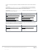
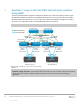
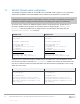
Table Of Contents
- 1 Introduction
- 2 Hardware overview
- 3 Leaf-spine overview
- 4 Protocols used in the leaf-spine examples
- 5 Layer 3 configuration planning
- 6 Example 1: Layer 3 with Dell EMC leaf and spine switches using OSPF
- 7 Example 2: Layer 3 with Dell EMC leaf and spine switches using eBGP
- A Dell EMC Networking ONIE switch factory default settings
- B Validated hardware and operating systems
- C Technical support and resources
- D Support and Feedback
28 Dell EMC Networking Layer 3 Leaf-Spine Deployment and Best Practices with OS10 | Version 1.0
Internal Use - Confidential
7 Example 2: Layer 3 with Dell EMC leaf and spine switches
using eBGP
This section provides eBGP configuration examples to build the layer 3 leaf-spine topology shown in Figure
13. Dell EMC Networking S4148F-ON and S4248FB-ON switches are used at the leaf layer and Dell EMC
Networking Z9100-ON switches are used at the spine layer. While the S4148F-ON configuration is shown in
this section, the configuration details for the S4248FB-ON switches are attached.
Note: The BGP ASNs and IP addresses defined in Section 5 are used here.
Rack 2Rack 1
S4248-Leaf4
Z9100-Spine1 Z9100-Spine2
S4248-Leaf3
VLTi
S4148-Leaf2
S4148-Leaf1
VLTi
Server 2
Server 1
L3 Connection
L2 Connection
ECMP
Eth 1/1/1-1/1/4
Eth 1/1/29-1/1/30
Eth 1/1/1Eth 1/1/1
Po 1
Po 1
Switch uplinks
Eth 1/1/25-1/1/26
IP Address 10.60.1.7/24
Gateway 10.60.1.1
Leaf 3
VLAN 60:
10.60.1.1/24
Leaf 4
VLAN 60:
10.60.1.2/24
IP Address 172.16.1.7/24
Gateway 172.16.1.1
Leaf 1
VLAN 50:
172.16.1.1/24
Leaf 2
VLAN 50:
172.16.1.2/24
Eth 1/1/47-1/1/48
Eth 1/1/1Eth 1/1/1
Eth 1/1/1-1/1/4
Switch uplinks
Eth 1/1/43-1/1/44
Example 2: Layer 3 leaf-spine topology
Note: All switch configuration files for the topology in Figure 13 are contained in the attachment named
Example2_config_files.pdf. The files may be edited as needed in a plain text editor and commands pasted
directly into switch consoles. Dell EMC Networking switches start at their factory default settings per
Appendix A.