Dell EMC Networking Layer 3 Leaf-Spine Deployment and Best Practices with OS10 Deploying layer 3 leaf-spine networks in the data center with Dell EMC Networking OS10 switches Dell EMC Networking Infrastructure Solutions March 2018 Internal Use - Confidential
Revisions Date Rev. Description Authors March 2018 1.0 Initial release Andrew Waranowski, Curtis Bunch THIS WHITE PAPER IS FOR INFORMATIONAL PURPOSES ONLY, AND MAY CONTAIN TYPOGRAPHICAL ERRORS AND TECHNICAL INACCURACIES. THE CONTENT IS PROVIDED AS IS, WITHOUT EXPRESS OR IMPLIED WARRANTIES OF ANY KIND. Copyright © 2018 Dell Inc. All rights reserved. Dell and the Dell EMC logo are trademarks of Dell Inc. in the United States and/or other jurisdictions.
Table of contents Revisions.............................................................................................................................................................................2 1 Introduction ...................................................................................................................................................................5 1.1 2 3 Hardware overview ....................................................................................................
6.3.4 show vlt vlt-port-detail .......................................................................................................................................26 6.3.5 show vlt mismatch ............................................................................................................................................26 6.3.6 show uplink-state-group ...................................................................................................................................26 6.3.
1 Introduction Data center networks have traditionally been built in a three-layer hierarchical tree consisting of access, aggregation and core layers as shown in Figure 1. Core Spine 1 Aggregation Access Hierarchical networking model Due to increasing east-west traffic within the data center (server-server, server-storage, etc.), an alternative to the traditional access-aggregation-core network model is becoming more widely used.
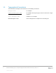
1.1 Typographical Conventions The command line examples in this document use the following conventions: 6 Monospace Text CLI examples Underlined Monospace Text CLI examples that wrap the page. This text is entered as a single command. Italic Monospace Text Variables in CLI examples Bold Monospace Text Used to distinguish CLI examples from surrounding text. Dell EMC Networking Layer 3 Leaf-Spine Deployment and Best Practices with OS10 | Version 1.
2 Hardware overview This section briefly describes the hardware used to validate the examples in this guide. A complete listing of hardware and components used is provided in Appendix B. 2.1 Dell EMC Networking S4148F-ON The Dell EMC Networking S4148F-ON is a 1-Rack Unit (RU) switch with forty-eight 10GbE ports and four 10/25/40/50/100GbE ports. In this guide, Two S4148F-ON switches are used as a leaf switches in the examples in this guide. Dell EMC Networking S4148F-ON 2.
3 Leaf-spine overview The following concepts apply to layer 3 leaf-spine topologies: Each leaf switch connects to every spine switch in the topology. Servers, storage arrays, edge routers and similar devices always connect to leaf switches, never to spines. Layer 3 topologies use two leaf switches at the top of each rack configured as a Virtual Link Trunking (VLT) pair. VLT allows all connections to be active while also providing fault tolerance.
4 Protocols used in the leaf-spine examples This section provides an overview of the protocols used in constructing the leaf-spine network examples in this guide. 4.1 VLT, Section 4.1 LACP/LAG, Section 4.2 Uplink Failure Detection (UFD), Section 4.3 RSTP, Section 4.4 Routing protocols, Section 4.5 - Border Gateway Protocol (BGP) - Open Shortest Path First (OSPF) VRRP, Section 4.6 ECMP, Section 4.
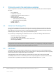
4.3 Uplink Failure Detection (UFD) If a leaf switch loses all connectivity to the spine layer, by default the attached hosts continue to send traffic to that leaf without a direct path to the destination. The VLTi link to the peer leaf switch handles traffic during such a network outage, but this is not considered a best practice. Dell EMC recommends enabling UFD, which detects the loss of upstream connectivity.
of switch misconfiguration or improperly connected cables. In properly configured and connected leaf-spine networks, there are no ports blocked by Spanning Tree Protocol. 4.5 Routing protocols Any of the following routing protocols may be used on layer 3 connections when designing a leaf-spine network: 4.5.1 OSPF BGP Border Gateway Protocol (BGP) BGP may be selected for scalability and is well suited for very large networks.
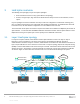
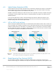
4.7 Equal Cost Multi-Path (ECMP) The nature of a leaf-spine topology is that leaf switches are no more than one hop away from each other. As shown in Figure 8, Leaf 1 has two equal cost paths to Leaf 4, one through each spine. The same is true for all leaf switches.
5 Layer 3 configuration planning 5.1 BGP ASN configuration When eBGP is used, an autonomous system number (ASN) is assigned to each switch. Valid private, 2-byte ASNs range from 64512 through 65534. Figure 9 shows the ASN assignments used for leaf and spine switches in the BGP examples in this guide.
10.0.1.1/32 10.0.2.1/32 10.0.2.2/32 10.0.1.2/32 10.0.2.3/32 Rack 1 10.0.2.4/32 Rack 2 Loopback addressing All loopback addresses used are part of the 10.0.0.0/8 address space with each address using a 32-bit mask. In this example, the third octet represents the layer, “1” for spine and “2” for leaf. The fourth octet is the counter for the appropriate layer. For example, 10.0.1.1/32 is the first spine switch in the topology while 10.0.2.4/32 is the fourth leaf switch. 5.2.
Note: Link labels A-D refer to S4148F switch ports, while link labels E-H refer to S4248FB switch ports. The point-to-point IP addresses used in this guide are shown in Figure 11: Spine 1 A Leaf 1 VLTi B C Spine 2 D E F Leaf 2 Rack 1 Point-to-point IP addresses 15 Dell EMC Networking Layer 3 Leaf-Spine Deployment and Best Practices with OS10 | Version 1.
6 Example 1: Layer 3 with Dell EMC leaf and spine switches using OSPF This section covers deploying a leaf-spine environment using OSPF with S4148F-ON and S4248FB-ON switches at the leaf layer and Z9100-ON switches used at the spine layer. While the S4148F-ON configuration is shown in this section the configuration provides OSPF configuration examples to build the layer 3 leaf-spine topology shown in Figure 12.
Note: All switch configuration files for the topology in Figure 12 are contained in the attachment named Example1_config_files.pdf. The files may be edited as needed in a plain text editor and commands pasted directly into switch consoles. Dell EMC Networking switches start at their factory default settings per Appendix A. 6.1 S4148F-ON leaf switch configuration The following configuration details are for S4148F-Leaf1 and S4148F-Leaf2 in Figure 12.
S4148F-Leaf1 S4148F-Leaf2 interface range ethernet 1/1/29-1/1/30 no switchport interface range ethernet 1/1/29-1/1/30 no switchport vlt-domain 127 backup destination 100.67.170.29 discovery-interface ethernet 1/1/29 discovery-interface ethernet 1/1/30 peer-routing vlt-domain 127 backup destination 100.67.170.30 discovery-interface ethernet 1/1/29 discovery-interface ethernet 1/1/30 peer-routing Create a server-facing VLAN interface. Use the same VLAN ID on both leaf switches.
Note: If multiple loopback interfaces exist on a system, the interface with the highest numbered IP address is used as the router ID. This configuration only uses one loopback interface. S4148F-Leaf1 S4148F-Leaf2 interface ethernet 1/1/25 description "Z9100-Spine1 eth 1/1/1" no switchport ip address 192.168.1.1/31 ip ospf 1 area 0 no shutdown interface ethernet 1/1/25 description "Z9100-Spine1 eth 1/1/2" no switchport ip address 192.168.1.
S4148F-Leaf1 S4148F-Leaf2 uplink-state-group 1 description "Disable downstream ports in event all uplinks fail" downstream port-channel 10 upstream ethernet 1/1/25 upstream ethernet 1/1/26 enable uplink-state-group 1 description "Disable downstream ports in event all uplinks fail" downstream port-channel 10 upstream ethernet 1/1/25 upstream ethernet 1/1/26 enable Enable OSPF globally and redistribute connected networks according to the previously defined route map.
Configure the four point-to-point interfaces connected to leaf switches. Assign IP addresses per Table 1. Configure a loopback interface to be used as the router ID. Enable OSPF on the interfaces with process 1 area 0. Note: If multiple loopback interfaces exist on a system, the interface with the highest numbered IP address is used as the router ID. This configuration only uses one loopback interface.
Configure a route map and IP prefix-list to redistribute all loopback addresses and leaf networks via BGP or OSPF. The command seq 10 permit 10.0.0.0/8 ge 24 includes all addresses in the 10.0.0.0/8 address range with a mask greater than or equal to 24. This includes all loopback addresses used as router IDs as well as the 10.60.1.0/24 network used on leaf switches 3 and 4 as shown in Figure 12. The command seq 20 permit 172.16.0.0/16 ge 24 includes the 172.16.1.
6.3 Example 1 validation In addition to sending traffic between hosts, the configuration shown in Figure 12 can be validated with the commands shown in this section. For more information on commands and output, see the Command Line Reference Guide for the applicable switch (links to documentation are provided in Appendix C). Command and output examples are provided for one spine and one leaf switch. Command output on other switches is similar. 6.3.
6.3.2 show ip route ospf This command is used to verify the OSPF entries in the Routing Information Base (RIB). Entries with multiple paths shown are used with ECMP. The two server networks in this example, 10.60.1.0 and 172.16.1.0, each have two paths from Z9100-Spine1, one through each leaf switch. The first set of routes with a subnet mask of /32 are the IPs configured for router IDs.
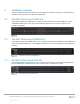
E2 - OSPF external type 2, * - candidate default, + - summary route, > - non-active route Gateway of last resort is not set Destination Gateway Dist/Metric Last Change -------------------------------------------------------------------------------O E2 10.0.1.1/32 via 192.168.1.0 ethernet1/1/25 110/20 00:15:34 O E2 10.0.1.2/32 via 192.168.2.0 ethernet1/1/26 110/20 00:15:27 O E2 10.0.2.2/32 via 192.168.1.0 ethernet1/1/25 110/20 00:15:27 via 192.168.2.0 ethernet1/1/26 O E2 10.0.2.3/32 via 192.168.1.
VLT Peer Unit ID System MAC Address Status IP Address Version -------------------------------------------------------------------------------1 14:18:77:25:56:b9 up fda5:74c8:b79e:1::1 1.0 6.3.4 show vlt vlt-port-detail This command is used to validate VLT LAG status on leaf switches in this topology. This command shows the status and active VLANs of all VLT LAGs (Port channel 10 in this example). The local and peer status must both be up.
Note: When an interface has been disabled by UFD, the show interfaces interface command for affected interfaces indicates it is error-disabled as follows: S4148F-Leaf-1#show interfaces te 1/4 TenGigabitEthernet 1/4 is up, line protocol is down(error-disabled[UFD]) -- Output truncated -- 6.3.7 show spanning-tree rstp brief This command validates that Spanning Tree Protocol is enabled on the leaf switches. All interfaces are forwarding (Sts column shows FWD).
7 Example 2: Layer 3 with Dell EMC leaf and spine switches using eBGP This section provides eBGP configuration examples to build the layer 3 leaf-spine topology shown in Figure 13. Dell EMC Networking S4148F-ON and S4248FB-ON switches are used at the leaf layer and Dell EMC Networking Z9100-ON switches are used at the spine layer. While the S4148F-ON configuration is shown in this section, the configuration details for the S4248FB-ON switches are attached.
7.1 S4148F-ON leaf switch configuration The following configuration details are for S4148F-Leaf1 and S4148F-Leaf2 in Figure 13. The configuration commands for S4248FB-Leaf3 and S4248FB-Leaf4 are similar and are provided in the attachments. Note: On S4148F-ON switches running OS10, Telnet is disabled and SSH is enabled by default. The S4148F-ON has default credentials of admin/admin. Therefore, the switch is accessible by default via SSH with those credentials.
Create a server-facing VLAN interface. Use the same VLAN ID on both leaf switches. Assign an IP address to the VLAN interface. The address must be unique but on the same network on both leaf switches. Configure VRRP to use VRRP version 3. Create a VRRP group and specify the group’s virtual IP address. Note: In this example, Server 1’s NIC is configured as an LACP NIC team. It is assigned the IP address 172.16.1.7/24. The VRRP VIP address, 172.16.1.254, is specified as Server 1’s default gateway.
S4148F-Leaf1 S4148F-Leaf2 interface ethernet 1/1/25 description "Z9100-Spine1 eth 1/1/1" no switchport ip address 192.168.1.1/31 no shutdown interface ethernet 1/1/25 description "Z9100-Spine1 eth 1/1/2" no switchport ip address 192.168.1.3/31 no shutdown interface ethernet 1/1/26 description "Z9100-Spine2 eth 1/1/1 no switchport ip address 192.168.2.1/31 no shutdown interface ethernet 1/1/26 description "Z9100-Spine2 eth 1/1/2" no switchport ip address 192.168.2.
description "Disable downstream ports in event all uplinks fail" downstream port-channel 10 upstream ethernet 1/1/25 upstream ethernet 1/1/26 enable description "Disable downstream ports in event all uplinks fail" downstream port-channel 10 upstream ethernet 1/1/25 upstream ethernet 1/1/26 enable Use these commands to configure eBGP. First, enable eBGP with the router bgp ASN command. The ASN is from Figure 9. The bgp bestpath as-path multipath-relax enables ECMP.
7.2 inherit template spine-leaf no shutdown inherit template spine-leaf no shutdown end write memory end write memory Z9100-ON spine switch configuration The following configuration details are for Z9100-ON-Spine1 and Z9100-ON-Spine2 in Figure 13. Set the host name, configure the OOB management interface and default gateway. Z9100-Spine1 Z9100-Spine2 enable configure t enable configure t hostname Z9100-Spine1 hostname Z9100-Spine2 interface mgmt 1/1/1 no ip address ip address 100.67.173.
interface ethernet 1/1/4 description "S4248FB-Leaf4 eth 1/1/47" no switchport ip address 192.168.1.6/31 no shutdown interface ethernet 1/1/4 description "S4248FB-Leaf4 eth 1/1/48" no switchport ip address 192.168.2.6/31 no shutdown interface loopback 0 description "Router ID" ip address 10.0.1.1/32 no shutdown interface loopback 0 description "Router ID" ip address 10.0.1.2/32 no shutdown Configure a route map and IP prefix-list to redistribute all loopback addresses and leaf networks via BGP or OSPF.
seconds hello and 180 seconds hold down) are for backup. The advertisement interval is set to one second. This is to prevent BGP speakers from advertising updates immediately upon receipt. Instead, they will advertise them in batched intervals of one second. This delay is to prevent overhead. Finally, exit configuration mode and save the configuration. 7.
Command and output examples are provided for one spine and one leaf. Command output on other switches is similar. 7.3.1 show ip bgp summary This command shows the status of all BGP connections. Each spine has four neighbors (the four leaf switches) and each leaf switch has two neighbors (the two spines switches). As can be seen, the leaf switches each use different ASNs, as the environment uses eBGP. 7.3.2 Z9100-Spine1#show ip bgp summary BGP router identifier 10.0.1.
B B B EX 10.0.2.3/32 EX 10.0.2.4/32 EX 10.60.1.0/24 B EX 172.16.1.0/24 B B B B EX EX EX EX 192.168.2.0/31 192.168.2.2/31 192.168.2.4/31 192.168.2.6/31 via via via via via via via via via via 192.168.1.5 192.168.1.7 192.168.1.5 192.168.1.7 192.168.1.1 192.168.1.3 192.168.1.1 192.168.1.3 192.168.1.5 192.168.1.
show vlt – see Section 6.3.3 show vlt vlt-port-detail– see Section 6.3.4 show vlt mismatch – see Section 6.3.5 show uplink-state-group – see Section 6.3.6 show spanning-tree rstp brief – see Section 6.3.7 38 Dell EMC Networking Layer 3 Leaf-Spine Deployment and Best Practices with OS10 | Version 1.
A Dell EMC Networking ONIE switch factory default settings Note: This set of instructions brings ONIE switches to their factory default settings, which includes removing the operating system. If only removing the configuration is desired, this can be achieved with delete startup-config proceeded with reload. All Dell EMC Networking ONIE switches in this guide can be reset to factory defaults with the following instructions: 1. Reboot the switch 2.
B Validated hardware and operating systems The following table includes the hardware and operating systems used to validate the examples in this guide. Switches and operating systems used in this guide 40 Switch OS / Version Dell EMC Networking S4148F-ON 10.4.0E(R3) Dell EMC Networking S4248FB-ON 10.4.0E(R3) Dell EMC Networking Z9100-ON 10.4.0E(R3) Dell EMC Networking Layer 3 Leaf-Spine Deployment and Best Practices with OS10 | Version 1.
C Technical support and resources Dell EMC TechCenter is an online technical community where IT professionals have access to numerous resources for Dell EMC software, hardware and services. Dell EMC TechCenter Networking Guides Manuals and documentation for Dell EMC Networking S4148F-ON Manuals and documentation for Dell EMC Networking S4248FB-ON Manuals and documentation for Dell EMC Networking Z9100-ON 41 Dell EMC Networking Layer 3 Leaf-Spine Deployment and Best Practices with OS10 | Version 1.
D Support and Feedback Contacting Technical Support Support Contact Information Web: Dell.com/support Telephone: USA: 1-800-945-3355 Feedback for this document We encourage readers to provide feedback on the quality and usefulness of this publication by sending an email to Dell_Networking_Solutions@Dell.com. 42 Dell EMC Networking Layer 3 Leaf-Spine Deployment and Best Practices with OS10 | Version 1.