
Deployment Guide


57 Leaf-Spine Deployment and Best Practices Guide | Version 1.0
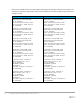
10 Example 4: Layer 2 with Dell EMC leaf and Cisco Nexus
spine switches
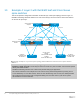
This section provides configuration information to build the layer 2 leaf-spine topology shown in Figure 17.
Dell EMC Networking Z9100-ON switches are used at the leaf layer and Cisco Nexus 7000 series switches
are used at the spine layer.
Rack 2
Spine 1-Nexus
7000
Leaf 4-Z9100 Leaf 3-Z9100
Leaf 2-Z9100
Leaf 1-Z9100
VLT i
Eth 3/1-4
Hu 1/31-1/32
Po 1 Po 2
Server 1 Server 2
Fo 1/3/1
VLT i
vPC Peer Lin k
Fo 1/1/1 Fo 1/3/1 Fo 1/3/1
Fo 1/1/1 Fo 1/1/1 Fo 1/3/1
Eth 3/1-4
Eth 3/5-6
Fo 1/1/1
VLAN 10, VLAN 20
Al l s pi ne s
VLAN 10, VLAN 20
All leafs
Spine 2-Nexus
7000
IP address :
192.168.20.21 and
192.168.10.11
IP address :
192.168.20.20 and
192.168.10.10
On both servers,
VLAN 10:
subnet 192.168.10.0/24
VLAN 20:
subnet 192.168.20.0/24
Te 1/33 Te 1/33 Te 1/33 Te 1/33
Hu 1/31-1/32
Rack 1
Example 4: Layer 2 leaf-spine topology with Dell EMC leaf and Cisco Nexus spine switches
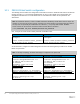
Note: All switch configuration files for the topology in Figure 17 are contained in the attachment named
Example4_config_files.pdf. The files may be edited as needed in a plain text editor and commands pasted
directly into switch consoles.
Dell EMC Networking switches start at their factory default settings per Appendix A.
Cisco Nexus switches in this example were reset to their factory default configurations by running write
erase followed by reload. After reload, "Power on Auto Provisioning" was not used, the admin password
was configured and the Nexus “basic configuration dialog” was not used. Refer to your Nexus system
documentation for more information.