
Deployment Guide

13 Leaf-Spine Deployment and Best Practices Guide | Version 1.0
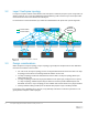
5 Protocols used in the leaf-spine examples
This section provides an overview of the protocols used in constructing the leaf-spine network examples in
this guide.
The first three protocols are used in all layer 2 and layer 3 topology examples:
• VLT, Section 5.1
• Uplink Failure Detection (UFD), Section 5.2
• RSTP, Section 5.3
The remaining protocols are only used in the layer 3 topology examples:
• Routing protocols, Section 5.4:
o Border Gateway Protocol (BGP)
o Open Shortest Path First (OSPF)
• Bidirectional Forwarding Detection (BFD), Section 5.5
• ECMP, Section 5.6
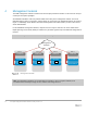
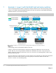
5.1 VLT
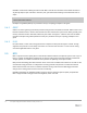
VLT allows link aggregation group (LAG) terminations on two separate switches and supports a loop-free
topology. The two switches are referred to as VLT peers and are kept synchronized via an inter-switch link
called the VLT interconnect (VLTi). A separate backup link maintains heartbeat messages across the OOB
management network.
VLT provides layer 2 multipathing and load-balances traffic. VLT offers the following additional benefits:
• Eliminates spanning tree-blocked ports
• Uses all available uplink bandwidth
• Provides fast convergence if either a link or device fails
• Assures high availability
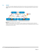
In layer 2 leaf-spine topologies, VLT is used at both the leaf and spine layers.
In layer 3 topologies, VLT is only used at the leaf layer. An additional feature called VLT peer routing is
enabled on the leaf switches for connections to layer 3 networks. VLT peer routing:
• Enables one VLT node to act as the default gateway for its VLT peer
• Eliminates the need to use Virtual Router Redundancy Protocol (VRRP)
• Enables active-active load sharing
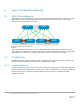
With peer routing enabled, traffic is routed through either VLT peer and is passed directly to the next hop
without needing to traverse the VLTi.