Dell Networking S3100 Series Getting Started Guide Regulatory Model: S3100
Notes, cautions, and warnings NOTE: A NOTE indicates important information that helps you make better use of your computer. CAUTION: A CAUTION indicates either potential damage to hardware or loss of data and tells you how to avoid the problem. WARNING: A WARNING indicates a potential for property damage, personal injury, or death. Copyright © 2016 Dell Inc. All rights reserved. This product is protected by U.S. and international copyright and intellectual property laws.
About this Guide 1 This document is intended as a Getting Started Guide to get new systems up and running and ready for configuration. For more details about S3100 series installation and software configuration, see the following information, available on the Dell Networking Support website (http://www.dell.com/support). • The Dell Networking S3100 Series Installation Guide describes installation and replacement procedures.
2 Installation This information describes installation of a S3100 series system. Dell Networking recommends completing the installation procedures in the order presented here. Operation and Safety Considerations Before installing the switch, review these operation and safety guidelines. Review these guidelines for switch installation: • You have enough clearance to the front of the switch so you can read the light emitting diodes (LEDs).
• Rack loading — Overloading or uneven loading of racks may result in shelf or rack failure, causing damage to the equipment and possible personal injury. Stabilize racks in a permanent location before loading begins. Mount the components starting at the bottom of the rack, then work to the top. Do not exceed your rack load rating. • Power considerations — Connect only to the power source specified on the unit.
Unpacking a S3100 Series Switch To unpack your switch, follow these steps. NOTE: Before unpacking the switch, inspect the container and immediately report any evidence of damage. When unpacking each S3100 series switch, make sure that the following items are included: • • • • • • • • • One S3100 series switch. One RJ-45 to DB-9 female cable. One Dell ReadyRails™ kit for rack installation, two mounting brackets, bolts, and cage nuts.
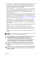
CAUTION: Do not use the mounted ReadyRails as a shelf or a workplace. NOTE: The illustrations in this document are not intended to represent a specific switch. 1U Tool-less Configuration To install the Dell ReadyRails system using the 1U tool-less configuration, follow these steps. 1. With the ReadyRails flange ears facing outward, place one rail between the left and right vertical posts. Align and seat the back flange rail pegs in the back vertical post flange.
of the rail) and remove each casting. Retain the castings for future rack requirements. It is not necessary to remove the rear flange castings. 2. Attach one rail to the front post flange with two user-supplied screws. See item 2 in the following figure. 3. Slide the plunger bracket forward against the vertical post and secure the plunger bracket to the post flange with two user-supplied screws. See item 3 in the following figure. 4. Repeat this procedure for the second rail. Figure 2.
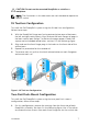
Two-Post Center-Mount Configuration To install the Dell ReadyRails system using the two-post center-mount configuration, follow these steps. 1. Slide the plunger bracket rearward until it clicks into place and secure the bracket to the front post flange with two user-supplied screws. See item 1 in the following figure. 2. Slide the back bracket towards the post and secure it to the post flange with two user-supplied screws. See items 2 and 3 of the following figure. 3.
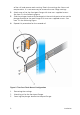
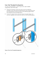
Four-Post Threaded Configuration To install the Dell ReadyRails system using the four-post threaded configuration, follow these steps. 1. Remove the flange ear castings from each end of the ReadyRails assemblies. Use a Torx driver to remove the two screws from each flange ear and remove each casting. See item 1 of the following figure. Retain the castings for future rack requirements. 2. For each rail, attach the front and rear flanges to the post flanges with two user-supplied screws at each end.
1. Removing the flange ear castings. 2. Attaching the rail flanges to the posts. Installing the System You can mount the system in the 1U front-rack or 1U two-post (flush and center) configurations. For the 1U two-post (flush and center) configurations, slide the system into the rails in the same manner as the four-post configurations. The following is an example of a 1U front-rack configuration. Installing a 1U Front-Rack Configure the rails that are attached to the system. 1.
3. 2. Front standoff with locking tab. After you have installed both switch rails, line them up on the previously mounted Ready-Rails and slide the switch in ( item 1 in the following figure) until it is flush with front of rack. About 3 inches before you fully insert your system, the rail locking feature (items 2 and 3) engages to keep the switch from inadvertently sliding out of the rack and falling. Figure 6. Installing the Switch in a Front-Rack Configuration 12 1. Chassis. 3.
Installing a Power Supply The S3100 systems are designed to support two hot-swappable power supplies (PSUs) with integrated fans that provide cooling for the chassis. 1. Remove the PSU from the electrostatic bag. 2. Remove the PSU slot cover from the switch. 3. Use the grab handle to slide the PSU into the switch PSU slot. The PSU slot is keyed such that the PSU can only be fully inserted in one orientation. The PSU slides into the slot smoothly.
WARNING: The PSU side includes two slots, PSU1 and PSU2. Although the switch can run on one PSU, Dell Networking highly recommends using two PSUs for full redundancy and additional cooling. To avoid overheating when the switch is running with only a single PSU, Dell Networking recommends using PSU1 (on the left when facing the PSU side) and covering the second PSU slot opening (PSU2) with a blank plate. CAUTION: To prevent electrical shock, ensure that the system is grounded properly.
Figure 8. Installing a Fan Tray Installing a Plug-In Module (Optional) The S3100 series switches support optional small form-factor pluggable plus (SFP+) or 10GBase-T modules. When hot swapping optional modules, the following module behaviors should be noted: • The configuration of the port is retained when an existing module is replaced with one that is the same. • Replacement of an optional module with one that is different results in the new module being moved into an error state.
Supply Power and Power Up the System Supply power after the switch is mounted in a rack or cabinet. Dell Networking recommends reinspecting your system prior to powering up. Verify that: • The equipment is properly secured to the rack. • The equipment rack is properly mounted and grounded. • The ambient temperature around the unit (which may be higher than the room temperature) is within the limits specified for the system. • There is sufficient airflow around the unit.
Installing the Software 3 This information describes the initial software configuration, including connecting, booting, configuration, and examples. Navigating CLI Modes The Dell Networking OS prompt changes to indicate the CLI mode. You can move linearly through the command modes, except for the end command that takes you directly to EXEC Privilege mode, and the exit command that moves you up one command mode level.
NOTE: You must have a password configured on a virtual terminal line before you can Telnet into the system. Therefore, use a console connection when connecting to the system for the first time. Before starting this procedure, be sure that you have a terminal emulation program already installed on your PC. NOTE: If you are configuring a stack of switches, serial console access to the stack manager is available from any serial port using the local CLI. Only one serial console session at a time is supported.
Console Port RJ-45 to RJ-45 Rollover Cable RJ-45 to RJ-45 Rollover Cable RJ-45 to Terminal DB-9 Adapter Server Device Signal RJ-45 Pinout RJ–45 Pinout DB-9 Pin Signal RxD 6 3 3 TxD NC 7 2 4 DTR CTS 8 1 7 RTS Default Configuration A version of Dell Networking OS is pre-loaded on the system; however, the system is not configured when you power up for the first time (except for the default host name, which is Dell). You must configure the system using the CLI.
Configuring a Host Name The host name appears in the prompt. The default host name is Dell. Host names must start with a letter, end with a letter or digit, and must have characters, letters, digits, and hyphens in the string. • Create a new host name. CONFIGURATION mode hostname name Accessing the System Remotely You can configure the system to be accessed remotely by Telnet. The system has a dedicated management port and a management routing table that is separate from the IP routing table. 1.
INTERFACE mode no shutdown Configuring the Management Route Define a path from the switch to the network from which you will remotely access the system. Management routes are separate from IP routes; they manage the system through the management port. • Configure a management route to the network from which you will access the system. CONFIGURATION mode management route ip-address/mask gateway Configuring the Username and Password To access the system remotely, configure a system username and password.
enable [password | secret] [level level] [encryptiontype] password Creating a Port-based VLAN The default local area network (VLAN), VLAN 1, is part of the system startup configuration and does not require configuration. To configure a port-based VLAN, create the VLAN and then add physical interfaces or port channel (LAG) interfaces to the VLAN. • Configure a port-based VLAN (if the vlan-id is different from the default VLAN ID) and enter INTERFACE VLAN mode.
interface vlan vlan-id 2. Enable an interface to include the IEEE 802.1Q tag header. INTERFACE mode tagged interface This command is available only in VLAN interfaces. 3. Move untagged interfaces. Access INTERFACE VLAN mode of the VLAN to which you want to assign the interface. CONFIGURATION mode interface vlan vlan-id 4. Configure an interface as untagged. INTERFACE mode untagged interface This command is available only in VLAN interfaces.
Configure an IP address and mask on the interface. Connect the System to the Network After you have completed the hardware installation and software configuration for the system, connect to your company network by following your company’s cabling requirements.
S3100 Series Technical Specifications 4 The following tables describe the technical specifications for the S3100 systems. CAUTION: Lithium Battery Caution: There is a danger of explosion if the battery is incorrectly replaced. Replace only with same or equivalent type. Dispose of the batteries according to the manufacturer's instructions. Table 2. S3100 Series Chassis Physical Design Parameter Specifications Height 1.71 inches (43.5 mm). Width 17.09 inches (434 mm). Depth 16.02 inches (407 mm).
Parameter Specifications Storage humidity 5 % to 90 % (RH), noncondensing. Maximum thermal output 24 port — 137.88 btu/hr. 48 port — 213.98 btu/hr. Maximum operational altitude 10,000 feet (3,048 meters) Maximum non-operational altitude 39,370 feet (12,000 meters) Table 4. Power Requirements Parameter Specifications Power supply 100–240 VAC 50/60 Hz. Maximum current draw per system (excluding PoE power) 24 port — 0.40 watts @40.41 watts/ 100vac, 0.20 watts @40.41 watts/ 200vac. 48 port — 0.