
Users Guide


another node, Node A, and Unit2 is linked to a node, Node C. When an NS traverses from Unit2 to Node B(ToR) and a
corresponding NA reaches Unit1 because of LAG hashing, this NA is tunneled to Unit 2 along with some control information.
The control information present in the tunneled NA packet is processed in such a way so that the ingress port is marked as the
link from Node B to Unit 2 rather than pointing to ICL link through which tunneled NA arrived.
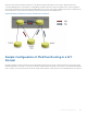
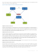
Figure 128. Sample Configuration of IPv6 Peer Routing in a VLT Domain
Sample Configuration of IPv6 Peer Routing in a VLT
Domain
Consider a sample scenario as shown in the following figure in which two VLT nodes, Unit1 and Unit2, are connected in a VLT
domain using an ICL or VLTi link. To the south of the VLT domain, Unit1 and Unit2 are connected to a ToR switch named Node
B. Also, Unit1 is connected to another node, Node A, and Unit2 is linked to a node, Node C. The network between the ToR and
Virtual Link Trunking (VLT) 906