
Users Guide


You can configure a VLT node to be an RP using the ip pim rp-address command in Global Configuration mode. When
you configure a VLT node as an RP, the (*, G) routes that are synchronized from the VLT peers are ignored and not downloaded
to the device. For the (S, G) routes that are synchronized from the VLT peer, after the RP starts receiving multicast traffic via
these routes, these (S, G) routes are considered valid and are downloaded to the device. Only (S, G) routes are used to forward
the multicast traffic from the source to the receiver.
You can configure VLT nodes, which function as RP, as Multicast source discovery protocol (MSDP) peers in different domains.
However, you cannot configure the VLT peers as MSDP peers in the same VLT domain. In such instances, the VLT peer does
not support the RP functionality.
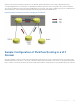
If the same source or RP can be accessed over both a VLT and a non-VLT VLAN, configure better metrics for the VLT VLANs.
Otherwise, it is possible that one VLT node chooses a non-VLT VLAN (if the path through the VLT VLAN was not available when
the route was learned) and another VLT node selects a VLT VLAN. Such a scenario can cause duplication of packets. ECMP is
not supported when you configure VLT nodes as RPs.
Backup RP is not supported if the VLT peer that functions as the RP is statically configured. With static RP configuration, if the
RP reboots, it can handle new clients only after it comes back online. Until the RP returns to the active state, the VLT peer
forwards the packets for the already logged-in clients. To enable the VLT peer node to retain the synchronized multicast routes
or synchronized multicast outgoing interface (OIF) maps after a peer node failure, use the timeout value that you configured
using the multicast peer-routing timeout value command. You can configure an optimal time for a VLT node to
retain synced multicast routes or synced multicast outgoing interface (OIF), after a VLT peer node failure, using the
multicast
peer-routing-timeout command in VLT DOMAIN mode. Using the bootstrap router (BSR) mechanism, you can configure
both the VLT nodes in a VLT domain as the candidate RP for the same group range. When an RP fails, the VLT peer
automatically takes over the role of the RP. This phenomenon enables resiliency by the PIM BSR protocol.
Configuring VLAN-Stack over VLT
To configure VLAN-stack over VLT, follow these steps.
1 Configure the VLT LAG as VLAN-Stack access or Trunk mode on both the peers.
INTERFACE PORT-CHANNEL mode
vlan-stack {access | trunk}
2 Configure VLAN as VLAN-stack compatible on both the peers.
INTERFACE VLAN mode
vlan-stack compatible
3 Add the VLT LAG as a member to the VLAN-stack on both the peers.
INTERFACE VLAN mode
member port-channel port—channel ID
4 Verify the VLAN-stack configurations.
EXEC Privilege
show running-config
Sample configuration of VLAN-stack over VLT (Peer 1)
Configure the VLT domain
Dell(conf)#vlt domain 1
Dell(conf-vlt-domain)#peer-link port-channel 1
Dell(conf-vlt-domain)#back-up destination 10.16.151.116
Dell(conf-vlt-domain)#primary-priority 100
Dell(conf-vlt-domain)#system-mac mac-address 00:00:00:11:11:11
Dell(conf-vlt-domain)#unit-id 0
Dell(conf-vlt-domain)#
Virtual Link Trunking (VLT) 901