
Users Guide


Enhanced VLT
An enhanced VLT (eVLT) configuration creates a port channel between two VLT domains by allowing two different VLT
domains, using different VLT domain ID numbers, connected by a standard link aggregation control protocol (LACP) LAG to
form a loop-free Layer 2 topology in the aggregation layer.
This configuration supports a maximum of four switches, increasing the number of available ports and allowing for dual
redundancy of the VLT. The following example shows how the core/aggregation port density in the Layer 2 topology is
increased using eVLT. For inter-VLAN routing and other Layer 3 routing, you need a separate Layer 3 router.
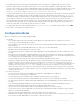
Figure 125. Enhanced VLT
VLT Terminology
The following are key VLT terms.
• Virtual link trunk (VLT) — The combined port channel between an attached device and the VLT peer switches.
• VLT backup link — The backup link monitors the vitality of VLT peer switches. The backup link sends configurable, periodic
keep alive messages between the VLT peer switches.
• VLT interconnect (VLTi) — The link used to synchronize states between the VLT peer switches.
• VLT domain — This domain includes both the VLT peer devices, VLT interconnect, and all of the port channels in the VLT
connected to the attached devices. It is also associated to the configuration mode that you must use to assign VLT global
parameters.
• VLT peer device — One of a pair of devices that are connected with the special port channel known as the VLT
interconnect (VLTi).
VLT peer switches have independent management planes. A VLT interconnect between the VLT chassis maintains
synchronization of L2/L3 control planes across the two VLT peer switches.
A separate backup link maintains heartbeat messages across an out-of-band (OOB) management network. The backup link
ensures that node failure conditions are correctly detected and are not confused with failures of the VLT interconnect. VLT
Virtual Link Trunking (VLT) 861