
Users Guide


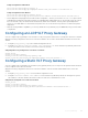
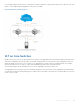

For more information about eVLT, refer to the Virtual Link Trunking (VLT) chapter. The core or Layer 3 routers C and D in local
VLT Domain and C1 and D1 in the remote VLT Domain are then part of a Layer 3 cloud.
Figure 122. Sample Configuration for a VLT Proxy Gateway
Guidelines for Enabling the VLT Proxy Gateway
Keep the following points in mind when you enable a VLT proxy gateway:
• Proxy gateway is supported only for VLT; for example, across a VLT domain.
• You must enable the VLT peer-routing command for the VLT proxy gateway to function.
• Asymmetric virtual local area network (VLAN) configuration, such as the same VLAN configured with Layer 2 (L2) mode on
one VLT domain and L3 mode on another VLT domain is not supported. You must always configure the same mode for the
VLANs across the VLT domain.
• You must maintain VLAN symmetry within a VLT domain.
• The connection between DCs must be a L3 VLT in eVLT format . For more information, refer to the eVLT Configuration
Example
• The trace route across the DCs can show extra hops.
• To ensure no traffic drops, you must maintain route symmetry across the VLT domains. When the routing table across DCs
is not symmetrical, there is a possibility of a routing miss by a DC that does not have the route for L3 traffic. Because routing
protocols are enabled and both DCs are in the same subnet, there is no dynamic route asymmetry. But if you configure a
static route on one DC and not on the other, there is asymmetry.
VLT Proxy Gateway 854