
Deployment Guide


143
C Appendix - Example of setting up a basic Ethernet L2
Bridging topology for end to end traffic with Ryu
The following section illustrates how to establish an end to end traffic flow using basic Ethernet Layer 2
bridging. The Ryu controller, a web browser and the REST API web utility Postman are used in these
examples, but any OpenFlow 1.3.4 compliant controller and REST API tool can be used.
Note: that Ryu 3.23 or later controller must be used for the example flows shown since it supports
JSON REST API calls properly.
Once DNOS-OF is set up on the switch, it is configured for management access, and a communication
channel is established to the controller and verified as described in the section on deployment, flows can
be set up and traffic tested.
The basic minimal steps required for creating a single end to end flow using DNOS-OF are shown below:
2) Set up a VLAN flow in the VLAN flow table.
3) Create a group that includes the proper VLAN flow and its associated port, and attaches it to an output
port that will be specified in the bridging flow.
4) Set up a bridging flow in the Bridging flow table to specify the output port.
The details of each of these flows required for end to end data traffic are outlined in the following
diagrams and the JSON scripts shown below. You can use XML, JSON, Java, C/C++, Perl, Python, or any
other mechanism to specify the metadata of the flow, as long as at the end of it the OpenFlow protocol
commands sent on the wire down to the switch describe the flow properly per the supported OpenFlow
protocol specification standard (currently V1.3.4 for Release 1.0 of DNOS-OF).
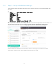
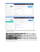
For the Ryu controller, you can use any REST API URL tool to retrieve switch information and to send and
retrieve flow information instructions which are then sent down to the switch via the controller using the
OpenFlow 1.3.4 protocol. The examples below show the use of the Ryu controller with a web browser
and with the Postman REST API application.
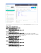
Once the switch datapath ID is retrieved, it can then be used to set up flows on the switch as shown below
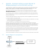
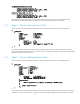
C.1 System Diagram for example flow
DNOS-OF switch
Flow Description in OF 1.3.4 protocol
port, table, match rules, instructions,
actions, etc.
Ryu Controller
<Ryu IP address>
Traffic port 2
VLAN 10
Transmit
Traffic port 5
VLAN 10
Receive