
Users Guide
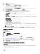
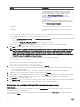

Table Of Contents
- Dell Lifecycle Controller Integration Version 3.3 for Microsoft System Center Configuration Manager User's Guide
- Introduction to Dell Lifecycle Controller Integration (DLCI) for Microsoft System Center Configuration Manager
- Use case scenarios
- Common prerequisites
- Editing and exporting the BIOS configuration profile of a system
- Comparing and updating the firmware inventory
- Creating, editing, and saving a RAID profile of a system
- Deploying operating system on collection
- Exporting server profile to iDRAC vFlash card or network share
- Importing server profile from iDRAC vFlash card or network share
- Viewing and exporting Lifecycle Controller logs
- Working With NIC or CNA Profiles
- Working with Fibre Channel profiles
- Selecting Fibre Channel storage area network in boot sequence
- Using Dell Lifecycle Controller Integration
- Licensing for DLCI
- Dell Deployment ToolKit
- Dell Driver CAB files
- Configuring target systems
- Auto-discovery and handshake
- Applying Drivers from the task sequence
- Creating a task sequence
- Creating a Dell specific task sequence
- Creating a custom task sequence
- Editing a task sequence
- Configuring the task sequence steps to apply operating system image and driver package
- Applying the operating system image
- Adding Dell driver packages
- Deploying a task sequence
- Creating a task sequence media bootable ISO
- System Viewer utility
- Configuration utility
- Launching the integrated Dell Remote Access Controller console
- Task Viewer
- Additional tasks you can perform with Dell Lifecycle Controller Integration
- Configuring security
- Validating a Dell factory-issued Client Certificate on the Integrated Dell Remote Access Controller for auto-discovery
- Pre-authorizing systems for auto-discovery
- Changing the administrative credentials used by Dell Lifecycle Controller Integration for Configuration Manager
- Using the Graphical User Interface
- Using the Array Builder
- Using the Configuration Utility
- Creating a Lifecycle Controller boot media
- Configuring hardware and deploying the operating system
- Deploying operating systems
- Hardware configuration and OS deployment workflow
- Updating firmware during OS deployment
- Configuring hardware during OS deployment
- Configuring RAID
- Applying a NIC or CNA profile on a collection
- Applying FC HBA profiles and FC SAN boot attributes on a collection
- Applying an integrated Dell Remote Access Controller profile on a collection
- Exporting the system profiles before and after hardware configuration
- Comparing and updating firmware inventory for systems in a collection
- Viewing the hardware inventory
- Verifying Communication with Lifecycle Controller
- Viewing and exporting Lifecycle Controller logs for a collection
- Modifying credentials on Lifecycle Controllers
- Platform restore for a collection
- Comparing NIC or CNA profiles against systems in a collection
- Using the Import Server Utility
- Using the System Viewer Utility
- Viewing and editing BIOS configuration
- Viewing and configuring RAID
- Configuring iDRAC profiles for a system
- Configuring NICs and CNAs for a system
- Configuring FC HBA cards for a system
- Comparing and updating firmware inventory
- Comparing hardware configuration profile
- Viewing Lifecycle Controller logs
- Viewing the hardware inventory for the system
- Platform restore for a system
- Comparing FC HBA profile against a target system
- Troubleshooting
- Configuring Dell provisioning web services on IIS
- Dell auto-discovery network setup specification
- Troubleshooting the viewing and exporting of Lifecycle Controller logs
- Deploying the operating system on Dell’s 13th generation of PowerEdge servers using WinPE 3.0
- Issues and resolutions
- ESXi or RHEL deployment on Windows systems moves to ESXi or RHEL collection, but not removed from Windows Managed Collection
- Related documentation and resources

Property Options
• Allow version upgrade only: Performs firmware update
on replaced parts if the firmware version of the new part
is lower than the original part.
• Match firmware of replaced part: Performs firmware
update on replaced parts to the version of the original
part.
• Do Not Change: Retains the default settings.
Part configuration update
• Disabled: Disables the operation that applies the current
configuration to a replaced part.
• Apply always: Applies the current configuration to the
replaced part.
• Apply only if firmware matches: Applies the current
configuration only if the current firmware matches with
the firmware of the replaced part.
• Do Not Change: Retains the default settings.
4. Click Finish after selecting the required options.
The following message is displayed: Task submission complete.
A task is submitted to the Task Viewer. You can launch the Task Viewer to view the status of the task. The task configures
the Lifecycle Controller of the system with the Part Replacement configuration. This configuration takes effect when you
replace any part for the system.
If you have updated the Part Replacement Attributes, sometimes the updates are not set immediately. Wait for couple of
minutes and check to see if the updates are set.
Comparing FC HBA profile against a target system
About this task
This feature enables you to generate a comparison report of how an FC HBA profile is applied to a target system and identify any
mismatches from the target system.
To generate a comparison report:
Steps
1. On the System Viewer utility, click Compare FC HBA Configuration Profile.
2. On the Compare FC HBA Configuration Profile screen, click Browse and select the FC HBA profile file that you have applied
to the collection.
A progress bar indicates that the target systems are scanned and an FC HBA comparison report is generated.
3. After the FC HBA comparison report is generated, the following colors are displayed on the screen to indicate the status of
comparison:
• White — indicates that the FC HBA profile that was applied and the profile on the target system are matching.
• Red — indicates that there is a mismatch while applying the FC HBA profile to the target system.
• Grey — indicates that either the FC HBA profile you applied is not configured, or the attribute is missing in the target
system.
4. The Compare FC HBA Configuration Profile screen displays the following fields:
• Target Adapter — the type of FC HBA adapter present on the target system. A target system can have multiple adapters.
• Location Applied — the location that is applied on the target system.
5. Select any record on the comparison report and click View Details to view the port details. The following fields are displayed.
• Attribute — lists the FC HBA attributes depending on the profile you have selected.
• System Value — lists the current value of the FC HBA attribute in the target system. If there are no values, the value
displayed is NA.
• Profile Value — lists the value of the FC HBA attributes in a profile. If there are no values, the value displayed is NA.
69