Dell Lifecycle Controller Integration Version 3.3 for Microsoft System Center Configuration Manager User's Guide 1 January 2017 Rev.
Notes, cautions, and warnings NOTE: A NOTE indicates important information that helps you make better use of your product. CAUTION: A CAUTION indicates either potential damage to hardware or loss of data and tells you how to avoid the problem. WARNING: A WARNING indicates a potential for property damage, personal injury, or death. Copyright © 2009 - 2017 Dell Inc. or its subsidiaries. All rights reserved. Dell, EMC, and other trademarks are trademarks of Dell Inc. or its subsidiaries.
Contents Chapter 1: Introduction to Dell Lifecycle Controller Integration (DLCI) for Microsoft System Center Configuration Manager................................................................................................... 7 What's new in this release................................................................................................................................................. 7 Existing features and functionalities.....................................................................
Applying drivers from Lifecycle Controller............................................................................................................ 22 Importing DLCI Dell server driver packages..........................................................................................................22 Viewing the condition for a fallback step.............................................................................................................. 23 Creating a task sequence............................
Comparing NIC or CNA profiles against systems in a collection........................................................................... 47 Chapter 5: Using the Import Server Utility.................................................................................. 48 Importing Dell servers...................................................................................................................................................... 48 Importing system variables..........................................
Issue 4............................................................................................................................................................................ 68 Issue 5............................................................................................................................................................................ 68 Issue 6...........................................................................................................................................
1 Introduction to Dell Lifecycle Controller Integration (DLCI) for Microsoft System Center Configuration Manager Dell Lifecycle Controller Integration (DLCI) for Microsoft System Center Configuration Manager (Configuration Manager) enables the administrators to leverage the remote enablement capabilities of Dell Lifecycle Controller, available as part of the Integrated Dell Remote Access Controller (iDRAC).
Table 1. New features and functionalities (continued) New feature Description Support for Dell’s 13th generation of PowerEdge servers With this version, you can configure the 13th generations of Dell PowerEdge servers through Integrated Dell Remote Access Controller (iDRAC) with Lifecycle Controller (LC) Existing features and functionalities Table 2.
Table 2. Features and functionalities (continued) Feature Functionality You can also compare the applied NIC/CNA profiles against the NIC/CNA configurations of the systems and generate comparison reports. For more information, see: ● Configuring NICs and CNAs for a system on page 54. ● Applying a NIC or CNA profile on a collection on page 39. ● Comparing NIC or CNA profiles against systems in a collection on page 47.
Table 2. Features and functionalities (continued) Feature Functionality System Viewer utility This feature enables you to configure individual systems by using the remote enablement capabilities of DLCI. For more information, see Using the System Viewer Utility on page 51. Config Utility This feature enables you to configure a collection of systems by using the remote enablement capabilities of Lifecycle Controller. For more information, see Using the Configuration Utility on page 34.
Supported Dell Systems and Operating Systems. In the Support Matrix, view the target systems and operating systems that are supported by Unified Server Configurator – Lifecycle Controller Enabled. Windows Preinstallation Environment (WinPE) compatibility matrix The following table lists the operating systems that can be deployed by DLCI for Configuration Manager and their respective WinPE environments. Table 3.
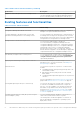
2 Use case scenarios This section describes typical use cases and tasks that you can perform with DLCI for Microsoft System Center Configuration Manager (Configuration Manager).
6. Save the profile as a .XML file to any folder location on the local system. Comparing and updating the firmware inventory You can use DLCI for Configuration Manager to compare and update the firmware inventory of a single system, or a collection of systems. You can compare the firmware inventory against a given inventory profile, Dell FTP site, or a PDK catalog created by Repository Manager. Prerequisites ● Common prerequisites on page 12.
2. Select RAID Configuration on the System Viewer utility to load the RAID configuration of the system. For more information, see Viewing and configuring RAID on page 53. 3. Launch Array Builder to create a RAID profile. For more information, see Creating a RAID Profile using Array Builder on page 29. 4. (Optional) Import and edit an existing profile. For more information, see Importing a profile on page 33. 5. Save the newly created RAID profile as a .XML file to any folder location on the local system.
● iDRAC vFlash card: ○ Installed as a license, enabled, and initialized NOTE: The iDRAC vFlash card is required only for Dell’s 11th generation of PowerEdge servers. For the 12th and 13th generation of PowerEdge servers, you must have an Enterprise license. ○ With a minimum free space of 384 MB available. ● Network Share: ○ Permissions and firewall settings are provided for the iDRAC to communicate with the system that has the network share.
● If you are importing from an iDRAC vFlash card, make sure that the card is installed and has the backup image in the SRVCNF partition. This image is from the same platform that you are importing. ● If you are importing from a network share, make sure that the network share where the backup image file is stored is still accessible. ● If you replace the motherboard before performing import, make sure that the motherboard has the latest iDRAC and BIOS installed.
Workflow for viewing and exporting Lifecycle Controller logs The following steps outline the workflow sequence: 1. To view the Lifecycle Controller logs of a single target system, launch the System Viewer utility. To view the Lifecycle Controller logs of a collection of systems, launch the Config Utility. For more information, see System Viewer utility on page 25 or Configuration utility on page 26. 2. Select View Lifecycle Controller Logs on the System Viewer utility or the Config Utility. 3.
● Create a profile — to create a new FC HBA profile. For more information, see Creating an FC HBA profile on page 57. ● Edit an existing profile — to edit an existing FC HBA profile. For more information, see Editing an FC HBA profile on page 58. 4. Add new adapter port or remove an adapter port from the profile. For more information, see steps 3 through 5 in Creating an FC HBA profile on page 57. 5. Select the adapter on the grid and configure it.
3 Using Dell Lifecycle Controller Integration This chapter discusses the various operations that you can perform after you install DLCI on Configuration Manager. Before you begin using DLCI for Configuration Manager, ensure that the target system is auto-discovered and present in the All Dell Lifecycle Controller Servers collection on the Configuration Manager console.
Dell Deployment ToolKit The Dell Deployment Toolkit (DTK) includes a set of utilities, sample scripts, and sample configuration files that you can use to deploy and configure the Dell systems. You can use DTK to build script-based and RPM-based installation for deploying large number of systems on a pre-operating system environment in a reliable way, without changing their current deployment processes.
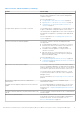
Use existing Boot Image from Configuration Manager This option allows you to select an existing boot image in Configuration Manager. Select an existing boot image from the drop-down list and use it to create a Dell boot image. Use a custom Boot Image Select this option to import a custom boot image from any other location. Specify the Universal Naming Convention (UNC) path of the Windows Imaging (WIM) file and select the boot image from the drop-down list.
Auto-discovery and handshake The auto-discovery and handshake feature enables the iDRAC on target systems to locate the provisioning service and establish communication with the Site Server. The Dell Provisioning service provisions a management account and updates Configuration Manager with the new system. The Dell Lifecycle Controller Utility (DLCU) for Configuration Manager uses the provisioned account to communicate with the iDRAC of target systems, to invoke the enabled features.
2. Right-click Driver Packages, select DLCI Server Driver Package → Import Dell DLCI Server Driver Package. The Dell DLCI Server Driver Package Import Wizard is displayed asking for the location of the Systems Management DVD. NOTE: If you have downloaded an ISO image, then create a physical disk or mount it on a virtual drive. 3. Select the drive in which you inserted the DVD and click Next. A list of driver packages for a combination of servers and operating systems is displayed. 4.
The Task Sequence Created window is displayed with the name of the task sequence you created. 10. Click Close in the confirmation message box that is displayed. Creating a custom task sequence 1. Launch the Configuration Manager Console. The Configuration Manager Console screen is displayed. 2. In the left pane, select Software Library > Overview > Operating Systems > Task Sequences. 3. Right-click Task Sequences, and then click Create Task Sequence. The Create Task Sequence Wizard is displayed. 4.
Adding Dell driver packages 1. In the left side of the Task Sequence Editor, under Deploy Operating System, click Apply Driver Package. 2. Click Browse. The Select a Driver Package window is displayed. 3. Click DLCI Driver Packages. A list of driver packages available in the Dell Lifecycle Controller Integration is displayed. 4. Select a package for a Dell PowerEdge server, such as Dell PEM630-Microsoft Windows 2012 R2-OM8.1.0. 5. Click Apply.
1. In Configuration Manager Version 1610, Configuration Manager 2012 SP2, Configuration Manager 2012 R2 SP1, Configuration Manager 2012 R2, Configuration Manager 2012 SP1, or Configuration Manager 2012 under Device Collections, right-click a Dell yx1x system or later and select Dell Lifecycle Controller > Launch System Viewer. The iDRAC Authentication Information screen displays the default credentials known to the Configuration Manager. 2.
After you install DLCI for Configuration Manager, you can view Dell Lifecycle Controller > Launch iDRAC Console menu option when you right-click on any system in the collection. You can also find the Launch iDRAC Console option when you select a system in the Task Viewer and right-click on it. To launch the iDRAC console for a system under the collection: 1.
Button Action View Log Click to view the log file that contains the details of the tasks that are running. Send to Taskbar Click to minimize the Task Viewer and send it to the task bar. Additional tasks you can perform with Dell Lifecycle Controller Integration Configuring security To configure security for DLCI, you must: ● Validate a Dell factory-issued Client Certificate on (iDRAC).
C:\Program Files (x86)\Dell\DPS\ProvisionWS\bin\import.exe –CIuserID [New Console Integration Admin User ID] To set the password: C:\Program Files (x86)\Dell\DPS\ProvisionWS\bin\import.exe -CIpassword [New Console Integration Admin Password] NOTE: The commands are case sensitive. Using the Graphical User Interface You can also use the Graphical User Interface (GUI) to change the security configurations. Use the following command to open the GUI screen: C:\Program Files (x86)\Dell\DPS\ProvisionWS\bin\import
● Create new arrays from a variable condition, if required. For more information, see Arrays on page 31. ● You can create an array, add additional disks, hot spares, or global hot spares to the array. 5. Click Save to save the profile as a .XML file. You can also import an existing profile and modify the configurations using the Array Builder. For more information on importing a profile, see Importing a profile on page 33.
NOTE: At least one controller is required on the server. If there is only one controller and you delete it, a message is displayed that the default controller was inserted because the last controller was deleted. Variable conditions To provide the ability to use the same RAID configuration in multiple logical configurations, variable evaluation is provided so that a different configuration for arrays and logical drives can be applied to different situations.
4. Click OK to apply the array, or Cancel to return to Array Builder. Editing an array To edit an array: 1. Select the array and click Arrays → Edit Array. The Array Settings window is displayed. You can select a different RAID level for the array. 2. Click OK to apply the changes, or Cancel to return to Array Builder. Deleting an array To delete an array: 1. Select the array and click Arrays → Delete Array. A message is displayed that all the attached disks will be deleted. 2.
● Standard disks — These are the basic, non-defined disk type that make up the storage on arrays. ● Hot Spares — These disks provide online redundancy if a RAID disk fails while assigned to a specific array. ● All Remaining Disks — These disks provide an option to define an array without specifying the exact number of disks. If the controller configuration specifies the number of disks required, an equivalent number of disks are added to the non-RAID group.
4 Using the Configuration Utility This section describes the various operations that you can perform with the Dell Lifecycle Controller Configuration Utility. You can use the Config Utility from the Configuration Manager console to: ● Create a new Lifecycle Controller boot media to deploy operating systems remotely. For more information, see Creating a Lifecycle Controller boot media on page 34. ● Configure hardware and deploy the operating system on the target systems in the collection.
NOTE: You can launch Config Utility for any collection. 2. In the Dell Lifecycle Controller Configuration Utility window, select Create new Lifecycle Controller Boot Media on the left-hand pane. 3. Click Browse and select the bootable ISO that you created. For more information, see Creating a task sequence media bootable ISO on page 25. 4. Specify the folder or path to save the Dell Lifecycle Controller boot media.
● Red Hat Enterprise Linux ● ESXi NOTE: After deploying non-windows operating systems, the service tag of the system name is displayed as host name in Configuration Manager console. ESXi installation is supported only on a hard disk for this release. For ESXi, Red Hat Enterprise Linux, the operating system is installed on the first disk with default configuration. For Red Hat Enterprise Linux, the following are set: ● Language is set to US ● Keyboard is set to US (U.S.
Hardware configuration and OS deployment workflow To deploy the operating system to a collection: 1. In Configuration Manager Version 1610, Configuration Manager 2012 SP2, Configuration Manager 2012 R2 SP1, Configuration Manager 2012 R2, Configuration Manager 2012 SP1, or Configuration Manager 2012, in Device Collections, right-click any appropriate Dell collection and select Dell Lifecycle Controller > Launch Config Utility. 2.
● Reboot to vFlash (ISO Must be present on vFlash) — Reboots to vFlash. Ensure that the ISO is present in the vFlash. NOTE: To use the Reboot to vFlash (ISO Must be present on vFlash) option, the label name of the partition created on vFlash must be ISOIMG. ● Select the Use Network ISO as Fallback check box if you want the network ISO to be a fallback step. ● Click Browse and select the path where the Dell Lifecycle Controller bootable media is saved.
1. Click Browse and select the hardware profile that you created using the System Viewer. This profile is applied during the operating system deployment process. For more information on creating hardware profiles, see Creating a new profile on page 52. 2. Select Continue on Error if you want to proceed to the next step even if this step fails. This option is selected by default. If you clear this option, the hardware configuration process is aborted when it encounters an error. 3.
4. Click Next to apply an iDRAC profile. NOTE: If there is an error while applying a NIC/CNA profile, the operating system deployment process continues to the next step. While applying an attribute using Config Utility, it does not check the dependent attributes value. After the hardware configuration task is complete, use Network Adapter Comparison Report in Config Utility to check if the attributes have been applied successfully.
● Include attributes in separate lines. For example: ○ New line: , , , ○ New line: , , , Provide the following FC SAN boot attributes for each HBA as mentioned in the CSV format: ● ● ● ● ● BootScanSelection — Specify the boot scan selection attribute. FirstFCTargetWWPN — Specify the first FC target world wide port name attribute. FirstFCTargetLUN — Specify the first FC target LUN attribute.
Table 6. iDRAC profile settings (continued) S.No Target Server Profile Settings What is Applicable ● Only vLAN ID and vLAN priority attributes from Advanced LAN settings. 3. Rack, Tower, or Blade system with Static IP address IPv4 Configuration attributes only. IPv4 address source is updated. 4. Rack, Tower, or Blade systems LAN Settings attributes only. Applied only to Rack and Tower systems and not to Blade systems. 5. Rack, Tower, or Blade systems Advanced LAN Settings attributes only.
3. Enter an Export File Passphrase. See step 4 in Exporting the system profile on page 62 to include an Export file passphrase that should be in a specific format. 4. Enter an Export File Name Prefix. NOTE: You can specify a file name prefix that is the same as an earlier Export file and in such situations, the Export file is overwritten.
5. Click Copy to Clipboard to copy the information to clipboard, or click Export to CSV to export the information in comma-separated values format. 6. Select the systems that you want to update with newer firmware and click Next. The screen displays the firmware download progress. 7. After the download is complete, click Next and choose one of the following options: ● Start now — to start the update immediately. ● Start on next boot — to start the update when the systems boot next.
1. In Configuration Manager Version 1610, Configuration Manager 2012 SP2, Configuration Manager 2012 R2 SP1, Configuration Manager 2012 R2, Configuration Manager 2012 SP1, or Configuration Manager 2012, in Device Collections, right-click All Dell Lifecycle Controller Servers and select Dell Lifecycle Controller > Launch Config Utility. 2. Select the View Lifecycle Controller Logs option.
The Out of Band Management Component Properties window is displayed. 2. Click the Dell Lifecycle Controller tab. 3. Under Local User Account on Lifecycle Controllers, click Modify. 4. In the New Account Information window, enter the new user name and new password. Confirm the new password and click OK. You have updated the new user name and password credentials in the Configuration Manager Database.
Configuring Part Replacement properties for a collection The steps to configure Part Replacement properties for a collection of systems are similar to that of configuring the properties for a single system. However, the check for valid licenses for the collection of systems is performed only after you complete configuring the other properties and submit the task.
5 Using the Import Server Utility This section describes the various activities that you can perform using the Import Server utility. This utility is installed when you install DLCI for Configuration Manager. For information on installing Dell Lifecycle Controller Integration for Configuration Manager, see the Installation Guide.
The managed server is displayed in green color. 6. Click Next and select the servers that you want to import. By default, all systems where the Authentication status is Success are selected. 7. Click Save As to save the report as a .CSV file in any location. 8. Specify the Target Collection under which you want the imported servers to be displayed and click Next. 9. Click Save As to save the report as a .CSV file in any location. 10. After the import process is complete, click Close to close the utility.
Table 7. Action And Description (continued) Action Description NA Not applicable 6. Select the variables you want to import. By default, the records with ADD and UPDATE actions on the grid are selected. The records with the DELETE action are not selected. You must select the record if you want to delete it from the system. You can also filter the records on the grid based on the system name. 7. Click Next. 8. Click Save As to save the report as a .CSV file in any location. 9.
6 Using the System Viewer Utility This chapter describes the operations that you can perform with the System Viewer Utility. You can use the System Viewer Utility to: ● View and edit the hardware configuration. For more information, see Viewing and editing BIOS configuration on page 51. ● View and edit the RAID configuration. For more information, see Viewing and configuring RAID on page 53. ● Create and edit iDRAC configuration profiles for your system.
NOTE: In Configuration Manager 2012, Operating system Deployment using UEFI boot mode is not supported. Creating a new profile To create a new profile: 1. In the BIOS Configuration screen, select Create a New Profile and click Next. The BIOS Attributes tab displays the BIOS attributes and current settings of the system. The Boot Sequence tab displays the boot sequence information of the system. 2.
Changing the BIOS or UEFI boot sequence and hard disk drive sequence To change the BIOS boot sequence and hard disk drive sequence: 1. In the BIOS Configuration screen, select Create a New Profile or Edit an Existing Profile, and click Browse to browse for the profile. 2. Click the Boot or UEFI Sequence tab. The current BIOS or UEFI boot sequence and hard disk drive sequence is displayed. 3. Use the Move Up and Move Down to change the BIOS or UEFI boot sequence or the hard disk drive sequence.
● ● ● ● LAN Settings Advanced LAN Settings Common IP Configuration IPv4 Configuration NOTE: For more information on the various parameters that you can set for the above attributes, see the Integrated Dell Remote Access Controller7/8 with Lifecycle Controller Version 2.30.30.30 available at Dell.com/support/home. 5. Click the Users tab. The grid retrieves the list of iDRAC users from the system and displays them. 6. You can add a user account or edit an existing user account.
For information on NICs supported by Lifecycle Controller, see the Dell Lifecycle Controller Unified Server Configurator/Unified Server Configurator-Lifecycle Controller Enabled User’s Guide available at Dell.com/support/manuals. Creating a NIC or CNA profile To create a NIC/CNA profile: 1. On the System Viewer utility, click Network Adapter Configuration. The options to create a new profile, edit an existing profile, or scan a collection to identify the adapters are displayed. 2.
The Adapter Configuration dialog box is displayed. 2. Select one of the following options: ● Configure adapter settings — to configure the settings. ● Copy settings from adapter — to copy the configuration settings from an adapter that is already configured. 3. Click Configure. The Configure Adapter dialog box is displayed. 4. Select the port that you want to configure and click Configure. 5. Select one of the following options: ● Configure port settings — to configure the port settings.
● DHCP Vendor ID — specify the DHCP Vendor ID in this field. If the Vendor Class ID field in the DHCP Offer packet matches the value in this field, the iSCSI boot host software looks for the required iSCSI boot extensions. You do not need to set this value if the iSCSI via DHCP option is disabled. ● LUN Busy Retry Count — specify the number of connection retries the iSCSI Boot initiator should attempt if the iSCSI target LUN is busy. 3. Click OK to save the configurations.
● ● ● ● ● Port Login Retry Count — Select to specify the number of times you try to log in. Port Login Timeout — Select to specify port login timeout. Port Down Retry Count — Select to specify port down retry count. Link Down Timeout — Select to specify link down timeout. Click OK to save the port settings and return to the FC HBA Configuration screen and configure other FC adapter ports before saving the profile.
CMC firmware cannot be updated directly from DLCI console. CMC cannot be updated using catalog, you can update the CMC using .bin or .cmc file from DRM repository. ● ● ● ● Component — displays the component names. Version — displays the firmware versions of the components. Baseline Version — displays the baseline versions of the components. Status — displays the status of the firmware and indicates whether the firmware of the system is same, or needs an update based on the repository selected.
● Password — Specify the correct password. 2. Click Next. The View Lifecycle Controller Logs screen is displayed. The screen displays the latest 100 logs by default. You can modify the number of logs to be displayed only when you click Pause or after all the 100 logs are displayed on the screen. The following details are displayed: Table 8. Lifecycle Controller log details Column Description Hostname This is the hostname of the system for which you are viewing the Lifecycle Controller logs.
● In the search field, filter information for the number of logs you have selected in the preceding step is displayed. 5. (Optional) To fetch fresh Lifecycle Controller logs from the system, click Refresh. 6. (Optional) When you are loading a large number of logs, you can click Pause to temporarily stop the loading of log files. During this phase, you can change the number of records you want to view by selecting the number from the drop-down list. 7. Click Resume to resume the loading of logs. 8.
Viewing the hardware inventory for the system You can use the System Viewer utility to view the hardware inventory details of the selected system. To view the hardware inventory for the system: On the System Viewer utility, select Hardware Inventory. The right-hand pane of the System Viewer utility displays the following details: ● Hardware Component — displays the name of the hardware component. ● Properties — displays the attributes of the hardware component.
NOTE: In a vFlash card, an existing system profile is overwritten when you export a system profile. ● Network share: backs up on a shared location on the network. If you choose this option you must specify the following information: ○ Existing share: Specify share location if you are creating a backup for the first time. This information is cached for subsequent backups and you can select the existing location from the drop-down box. ○ User name: Specify the user name to access the share location.
3. Select one of the following options: ● vFlash media: to restore the backup image from the iDRAC vFlash Card. ● Network share: to restore the backup image from a shared location on the network. If you choose this option, you must specify the following information: ○ Existing share: specify share location where you have saved the backup image. The drop-down list contains the list of shares where you had previously created backup files for the system or collection.
Table 9. Property and options (continued) Property Options Part configuration update ● Disabled: Disables the operation that applies the current configuration to a replaced part. ● Apply always: Applies the current configuration to the replaced part. ● Apply only if firmware matches: Applies the current configuration only if the current firmware matches with the firmware of the replaced part. ● Do Not Change: Retains the default settings. 4. Click Finish after selecting the required options.
7 Troubleshooting This topic list the issues and steps to troubleshoot them. Topics: • • • • • • Configuring Dell provisioning web services on IIS Dell auto-discovery network setup specification Troubleshooting the viewing and exporting of Lifecycle Controller logs Deploying the operating system on Dell’s 13th generation of PowerEdge servers using WinPE 3.
Dell auto-discovery network setup specification For information on auto-discovery error messages, descriptions, and response actions, see the Dell Auto-Discovery Network Setup Specification document at delltechcenter.com Troubleshooting the viewing and exporting of Lifecycle Controller logs When you view the Lifecycle Controller logs for a single system or a collection, the grid view can display the following values — -1 in the No. Column, Not Available in the Category, Description, and ID columns.
Resolution: This is because the network does not assign IP addresses fast enough. To avoid this issue, ensure that you enable Spanning Tree and Fast Link on the network switch. Issue 2 Issue: If the Lifecycle Controller of a system is in use, the system is not discovered. Resolution: If a system does not show up in a collection, verify whether the log file contains the following error message: Lifecycle Controller in use. If it contains the error message: 1.
Issue 8 Issue: If the Lifecycle Controller on the target system is locked by another process, the following error message is displayed in the DLCTaskManager.log file: Lifecycle Controller is being used by another process. Resolution: Ensure that the iDRAC of your system is not in POST state.
To re-enable the Apply option: 1. Right-click the task sequence and select Edit. 2. Select Restart in Windows PE. In the Description section, type any character and delete it so the change is not saved. 3. Click OK. This re-enables the Apply option. Issue 15 Issue: The System Viewer Utility does not display the latest RAID configuration. Resolution: When you are viewing the RAID configuration for a system using the System Viewer Utility, the information is cached.
Issue 22 Issue: When you continuously add Lifecycle Controller Logs, or one or more of the components continuously create log entries, you may not view the Lifecycle Controller Logs for the collection. Resolution: To view the Lifecycle Controller Logs, click Refresh on the Lifecycle Controller Logs screen after waiting for a short period. Issue 22 Issue: Creation of unattended operating system media takes a long time in a non-windows operating system deployment.
8 Related documentation and resources For more information on Configuration Manager such as installation, features, and functionalities, see the Microsoft TechNet site at technet.microsoft.com. In addition to this guide, you can access the following guides available at Dell.com/support/manuals. On the Manuals page, click Software and Security > System Management.
2. Click Browse all products. 3. From the All products page, click Software, and then click the required link. 4. Click the required product and then click the required version. Using search engines, type the name and version of the document in the search box.