Dell Lifecycle Controller Integration Version 3.
Notes, cautions, and warnings NOTE: A NOTE indicates important information that helps you make better use of your computer. CAUTION: A CAUTION indicates either potential damage to hardware or loss of data and tells you how to avoid the problem. WARNING: A WARNING indicates a potential for property damage, personal injury, or death. Copyright © 2009 - 2015 Dell Inc. All rights reserved. This product is protected by U.S. and international copyright and intellectual property laws.
Contents 1 Introduction to Dell Lifecycle Controller Integration (DLCI) for Microsoft System Center Configuration Manager.............................................8 What's new in this release..................................................................................................................... 8 Existing features and functionalities..................................................................................................... 9 Supported operating systems..............................
Licensing for DLCI...............................................................................................................................20 Dell Deployment ToolKit.................................................................................................................... 20 Dell Driver Cab Files............................................................................................................................ 21 Importing a Dell Driver Cab files.......................................
Hardware configuration and OS deployment workflow..............................................................41 Updating firmware during OS deployment..................................................................................43 Configuring hardware during OS deployment............................................................................ 43 Configuring RAID..........................................................................................................................
Downloading and updating the 11th and 12th generation message registry............................. 67 Downloading and updating the 13th generation message registry............................................ 67 Viewing the hardware inventory for the system................................................................................ 67 Platform restore for a system.............................................................................................................
Accessing documents from Dell support site...................................................................................
Introduction to Dell Lifecycle Controller Integration (DLCI) for Microsoft System Center Configuration Manager 1 Dell Lifecycle Controller Integration (DLCI) for Microsoft System Center Configuration Manager (Configuration Manager) enables the administrators to leverage the remote enablement capabilities of Dell Lifecycle Controller, available as part of the Integrated Dell Remote Access Controller (iDRAC).
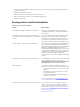
• Inventory Export for CMC is supported in this release, which is used by Dell Repository Manager for creation of repository • Support for Dell driver cab files • Removal of Dell Server Deployment Pack dependency • Removal of Dell Connections License Manager dependency • Support for ESXI 6.0 Existing features and functionalities Table 1.
Feature Functionality Configure network interface cards (NICs) and converged network adapters (CNAs) You can configure different attributes of specific NICs or CNAs in the system and save them to a profile. The saved profiles can later be applied to the collection as part of the hardware configuration or operating system deployment, or both. You can also compare the applied NIC/CNA profiles against the NIC/CNA configurations of the systems and generate comparison reports.
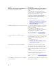
Feature Functionality Schedule firmware updates You can schedule updates for firmware. For more information, see Comparing and Updating Firmware Inventory. Configure certificate authority (CA) and common name (CN) checks You can configure CA and CN checks for DLCI communication with the targets. Auto-discovery and Handshake This feature enables the iDRAC on bare metal systems to locate the provisioning service and establish communication with the Site Server.
Dell System Software Support Matrix → Dell System Software Support Matrix → View → Supported Dell Systems and Operating Systems. In the Support Matrix, view the target systems and operating systems that are supported by Unified Server Configurator – Lifecycle Controller Enabled. Windows Preinstallation Environment (WinPE) compatibility matrix The following table lists the operating systems that can be deployed by DLCI for Configuration Manager and their respective WinPE environments. Table 2.
Use case scenarios 2 This section describes typical use cases and tasks that you can perform with DLCI for Microsoft System Center Configuration Manager (Configuration Manager). Common prerequisites Before working on the user scenarios, it is recommended that you complete the following prerequisites. • In Configuration Manager 2012, make sure that the system is discovered and present under Assets and Compliance → Device Collections → All Dell Lifecycle Controller Servers.
Creating, editing, and saving a RAID profile of a system You can create, edit, and save the RAID profile of a system and apply it when you deploy an operating system to a collection of systems on the Configuration Manager console. Prerequisites • Common Prerequisites • RAID controller and firmware that supports Local Key Management Workflow 1. Launch the System Viewer utility on the Configuration Manager console for a particular system. For more information, see System Viewer Utility. 2.
3. For a single system, see Comparing and Updating Firmware Inventory. 4. For a collection, see Comparing and Updating Firmware Inventory for Systems in a Collection. Deploying operating system on collection You can use DLCI for Configuration Manager to deploy an operating system on a collection of systems on the Configuration Manager console. Prerequisites • Common Prerequisites. • Select the Driver Cab which is compatible with the boot image (WinPE version).
• iDRAC vFlash card: – Installed as a license, enabled, and initialized. NOTE: The iDRAC vFlash card is required only for Dell’s 11th generation of PowerEdge servers. For the 12th and 13th generation of PowerEdge servers, you must have an Enterprise license. – With a minimum free space of 384 MB available. • Network Share: – Permissions and firewall settings are provided for the iDRAC to communicate with the system that has the network share. – With a minimum free space of 384 MB available.
• iDRAC vFlash card: – Is installed as a license, enabled and has the SRVCNF partition. In Lifecycle Controller, during backup, a partition with a label name SRVCNF is automatically created on the vFlash SD card to store the backup image file. If a partition with the label name SRVCNF already exists, it is overwritten. For more information, see Lifecycle Controller documentation at dell.com/support/ manuals. – Has minimum free space of 384 MB available.
• Configure the number of log files you want to view at a time in the DLCSystemview.exe.config or the DLCConfigUtility.exe.config files. For more information, see Viewing Lifecycle Controller Logs.
7. Save the NIC or CNA profile.
Using Dell Lifecycle Controller Integration 3 This chapter discusses the various operations that you can perform after you install DLCI on Configuration Manager. Before you begin using DLCI for Configuration Manager, ensure that the target system is auto-discovered and present in the All Dell Lifecycle Controller Servers collection on the Configuration Manager console.
NOTE: If the folders containing boot critical drivers are not present, then the wizard will display an error message. Dell Driver Cab Files A cabinet (.cab) file is a compressed file that contains other distribution files, such as drivers and system files. The Dell driver CAB file provides a new levels of flexibility for creating and deploying customized OS images on Dell Enterprise Client systems with deployment tools like Configuration Manager. Importing a Dell Driver Cab files 1.
Use Boot Image from WAIK/ADK tools Select this option to create both x64 and x86 Dell boot images. The source for the boot image creation is obtained from Windows Automated Installation Kit (WAIK) or Windows Assessment and Deployment Kit (ADK), depending on the configuration, and all the Windows PE custom install packages are added to the boot image. Use existing Boot Image from Configuration Manager This option allows you to select an existing boot image in Configuration Manager.
To enable CSIOR for earlier server generations: 1. Restart the system. 2. During Power-on Self-Test (POST), when the system prompts you to enter the iDRAC Utility, press < E>. 3. Select System Services from the options available and press . 4. Select Collect System Inventory on Restart and press the right or down keys and set it to Enabled. To enable CSIOR for Dell’s 13th generation and 12th generation of PowerEdge servers: 1. Select during POST to enter System Setup. 2.
NOTE: If you edit the task sequence to which drivers are exposed from the Lifecycle Controller option checked, the errors in step 7 may not be reflected in the step status and in the Missing Objects dialog box. Configure the Apply Drivers from Dell Lifecycle Controller option before you apply the changes. 1. Create a new task sequence if there is no existing task sequence, or edit the task sequence to which drivers are exposed from the Lifecycle Controller. 2. Select Apply Operating System Images. 3.
Viewing the condition for a fallback step The condition DriversNotAppliedFromLC is automatically added by DLCI for Configuration Manager while creating a task sequence. This condition is used as a fallback step if the application of drivers from Lifecycle Controller fails. NOTE: It is recommended that you do not disable or delete the condition. To view the condition for a fallback step: 1.
10. Click Close in the confirmation message box that is displayed. Creating a custom task sequence 1. Launch the Configuration Manager Console. The Configuration Manager Console screen is displayed. 2. In the left pane, select Software Library → Overview → Operating Systems → Task Sequences. 3. Right-click Task Sequences, and then click Create Task Sequence. 4. Select Create a new custom task sequence, and click Next. The Create Task Sequence Wizard is displayed. 5.
To apply the operating system image: 1. In the left side of the Task Sequence Editor, under Deploy Operating System, click Apply Operating System Image. 2. Select one of the following options: • 3. Apply operating system from a captured image • Apply operating system from an original installation source Browse and select the operating system location and click OK. Adding Dell driver packages 1. In the left side of the Task Sequence Editor, under Deploy Operating System, click Apply Driver Package.
5. Clear the Protect Media with a Password check box and click Next. 6. Browse and select Dell PowerEdge Server Deployment Boot Image. 7. Select the distribution point from the drop-down menu, and select the Show distribution points from child sites check box. 8. Click Next. The Summary screen appears with the task sequence media information. 9. Click Next. The progress bar is displayed. 10. On completion, close the wizard.
feature of the Lifecycle Controller present on Dell systems. You can perform the various operations on all the target systems at one time. To launch the Configuration Utility: 1. In Configuration Manager 2012 SP2, Configuration Manager 2012 R2 SP1, Configuration Manager 2012 R2, Configuration Manager 2012 SP1, or Configuration Manager 2012 under Device Collections, right-click on All Dell Lifecycle Controller Servers and select Dell Lifecycle Controller → Launch Config Utility.
Launching the integrated Dell Remote Access Controller Console from the Task Viewer To launch the iDRAC console from the Task Viewer: 1. Launch the Task Viewer by clicking the Dell icon on the task bar. This icon is displayed when you are deploying the operating system on the Dell systems, or you are applying firmware updates on the systems, or performing both the actions. For more information on deploying the operating system, see Configuring Hardware and Deploying the Operating System.
Button Action Export Queue Click to export the current state of the tasks in the Task Viewer to a .CSV file. You can use the .CSV to view the summary of the total number of DLCI tasks that are running. View Log Click to view the log file that contains the details of the tasks that are running. Send to Taskbar Click to minimize the Task Viewer and send it to the task bar.
Running the command creates a record for each service tag in the repository file Program Files]\Dell\DPS \Bin\Repository.xml. This feature is disabled by default. To enable this authorization check, run the following command: C:\Program Files (x86)\Dell\DPS\ProvisionWS\bin\import.exe –CheckAuthorization true.
You can also apply configuration rules based on the RAID profiles detected on the server. This allows you to define different configurations to different servers even if the detected hardware is identical. Creating a RAID Profile Using Array Builder To create a RAID Profile: You can also import an existing profile and modify the configurations using the Array Builder. For more information on importing a profile, see Importing a Profile. 1.
• All remaining controllers NOTE: If the disk(s) is set to non-RAID, the existing RAIDs are cleared when the variable condition is not met. Adding a Controller To add a controller: 1. Select a controller from the list, or select an embedded controller. The Controllers drop-down menu to your left is enabled. 2. Click Controllers→ New Controller . The Controller Configuration window is displayed. 3.
NOTE: DLCI for Configuration Manager does not support variables created in an encrypted format. Adding a new variable condition To add a new variable condition: 1. Under an embedded controller, expand Embedded Controller, and select [No variable conditions defined]. 2. Click Variables→ New Variable Condition. The Variable Condition Configuration window is displayed. 3. Under Variable Matching Criteria, you can set a rule to apply this variable only if it matches certain criteria that you select. 4.
Editing an array To edit an array: 1. Select the array and click Arrays→ Edit Array. 2. Click OK to apply the changes, or Cancel to return to Array Builder. The Array Settings window is displayed. You can select a different RAID level for the array. Deleting an array To delete an array: 1. Select the array and click Arrays→ Delete Array. 2. Click Yes to delete or No to cancel. A message is displayed that all the attached disks will be deleted.
Disks (array disks) Disks can be part of arrays (or the non-RAID disks node) and are of the following types: • Standard disks — These are the basic, non-defined disk type that make up the storage on arrays. • Hot Spares — These disks provide online redundancy if a RAID disk fails while assigned to a specific array. • All Remaining Disks — These disks provide an option to define an array without specifying the exact number of disks.
Using the Configuration Utility 4 This section describes the various operations that you can perform with the Dell Lifecycle Controller Configuration Utility. You can use the Config Utility from the Configuration Manager console to: • Create a new Lifecycle Controller boot media to deploy operating systems remotely. For more information, see Creating a Lifecycle Controller Boot Media. • Configure hardware and deploy the operating system on the target systems in the collection.
To create a Lifecycle Controller boot media: 1. In Configuration Manager 2012, under Device Collections, right-click All Dell Lifecycle Controller Servers and select Dell Lifecycle Controller → Launch Config Utility. NOTE: You can launch Config Utility for any collection. 2. In the Dell Lifecycle Controller Configuration Utility window, select Create new Lifecycle Controller Boot Media on the left-hand pane. 3. Click Browse and select the bootable ISO that you created.
Deploying operating systems You can deploy Windows and non-Windows operating systems on a collection and the operating system deployment is only supported for deploying operating systems on multiple servers. During the operating system deployment, the status and progress of installation is displayed in the DLCI task viewer. After installing the operating system, the system is added to a collection and is identified as Managed Dell Lifecycle Controller Servers.
• @perl-runtime • @server-platform • @server-policy • pax • python-dmidecode • oddjob • sgpio • certmonger • pam_krb5 • krb5-workstation • perl-DBD-SQLite For deploying ESXi, use the Dell customized ISO available at dell.com/support/home. Provide the ISO share on a NFS share. This share is used by DLCI to extract the ISO and create a custom ISO. The custom ISOes are saved on the same share. It is recommended that the machine with the NFS share is not connected to the Internet.
Select Continue on Error, to continue the deployment, even if there is an error. 6. Select Configure Hardware if you want to make changes to the hardware settings. For more information, see Configuring Hardware During OS Deployment. 7. Click Next. 8. Select Configure RAID to configure RAID on the servers. For more information, see Configuring RAID. 9. Click Next. 10. Select Configure network adapter if you want to apply a Network adapter profile to the collection.
NOTE: If you want to update a system after you deploy the operating system, and the system services are still unavailable, then you can reset the iDRAC using the iDRAC web-based interface. For more information, see the Dell Lifecycle Controller Remote Services User’s Guide available at dell.com/support/manuals. After the deployment is successful, the system with iDRAC moves to the Managed Dell Lifecycle Controller (OS Deployed) collection under All Dell Lifecycle Controller Servers.
Configuring RAID To configure RAID: 1. Click Browse and select the RAID profile that you created using the System Viewer utility. This profile is applied during the operating system deployment process. For more information on creating RAID profiles, see Using the Array Builder. 2. Click Next to configure network adapters.
4. S.No Target Server Setting Profile Settings What is Applied 4. Dual Port Quad Partition Dual Port NIC Dual Port Quad Partition NIC Dual Port Quad Partition NIC 5. Dual Port Quad Partition Dual Port NIC NIC 6. Dual Port Quad Partition Dual Port Quad Partition Dual Port Quad Partition NIC NIC Nothing is applied as there is no match between the target server setting and profile setting. Click Next to apply an iDRAC profile.
S.No Target Server Profile Settings What is Applicable 4. Rack, Tower, or Blade systems LAN Settings attributes only. Applied only to Rack and Tower systems and not to Blade systems. 5. Rack, Tower, or Blade systems Advanced LAN Settings attributes only. All Advanced LAN Settings attributes are applied to Rack and Tower systems. Only vLAN ID and vLAN priority attributes are applied to Blade systems. 3. 6. Rack, Tower, or Blade systems Common IP Configuration attributes only.
To compare and update firmware inventory: 1. In Configuration Manager 2012 SP2, Configuration Manager 2012 R2 SP1, Configuration Manager 2012 R2, Configuration Manager 2012 SP1, or Configuration Manager 2012, under Device Collections, right-click All Dell Lifecycle Controller Servers and select Dell Lifecycle Controller → Launch Config Utility. 2. From the left pane of the Dell Lifecycle Controller Configuration Utility, select Firmware Inventory, Compare, and Update. 3.
Collections, right-click All Dell Lifecycle Controller Servers and select Dell Lifecycle Controller → Launch Config Utility. 2. On the Dell Lifecycle Controller Configuration Utility, select Hardware Inventory. The following details are displayed on the right pane of the Dell Lifecycle Controller Configuration Utility: • Name: displays the name of the Dell system, which is part of the collection. • Hardware: displays the hardware components of the system. For example, Memory, CPU, and iDRAC.
Collections, right-click All Dell Lifecycle Controller Servers and select Dell Lifecycle Controller → Launch Config Utility. 2. From the left pane of the Dell Lifecycle Controller Configuration Utility, select Modify Credentials on Lifecycle Controllers. 3. Type the current user name and password, and the new user name and password. You can provide user credentials authenticated on active directory. NOTE: You cannot enter specific special characters in the user name field.
To view the Lifecycle Controller logs for a collection: 1. In Configuration Manager 2012 SP2, Configuration Manager 2012 R2 SP1, Configuration Manager 2012 R2, Configuration Manager 2012 SP1, or Configuration Manager 2012, under Device Collections, right-click All Dell Lifecycle Controller Servers and select Dell Lifecycle Controller → Launch Config Utility. 2. Select the View Lifecycle Controller Logs option.
To launch the Platform Restore screen for a collection: 1. In Configuration Manager 2012 SP2, Configuration Manager 2012 R2 SP1, Configuration Manager 2012 R2, Configuration Manager 2012 SP1, or Configuration Manager 2012, under Device Collections, right-click All Dell Lifecycle Controller Servers and select Dell Lifecycle Controller → Launch Config Utility. 2. Select the Platform Restore option.
3. On the Network Adapter Comparison Report screen, click Browse and select the NIC/CNA profile file that you have applied to the collection. A progress bar indicates that the target systems are scanned and a comparison report is generated. 4. After the comparison report is generated, the following colors are displayed: • White — indicates that the profile that was applied and the profile on the target system are matching.
Using the Import Server Utility 5 This section describes the various activities that you can perform using the Import Server utility. This utility is installed when you install DLCI for Configuration Manager. For information on installing Dell Lifecycle Controller Integration for Configuration Manager, see the Installation Guide.
The iDRAC Authentication process verifies the iDRAC credentials you have provided when you install DLCI for Configuration Manager against each of the iDRAC IP addresses you have specified. The grid displays the IP Address, name of the server, and the status of the authentication. You can provide user credentials authenticated on active directory.
• Value in the .CSV file — The value of the variable in the .CSV file. If the variable is not present in the file, this column displays the value NA. • Value in the System — The value of the variable in the system. If the variable is not present on the system, this column displays the value NA. • Action — The action to be taken for the variable. This action always gives precedence to the variables and the values present in the .CSV file. Table 5. Action And Description 6.
Using the System Viewer Utility 6 This chapter describes the operations that you can perform with the System Viewer Utility. You can use the System Viewer Utility to: • View and edit the hardware configuration. For more information, see Viewing and Editing BIOS Configuration. • View and edit the RAID configuration. For more information, see Viewing and Configuring RAID. • Create and edit iDRAC configuration profiles for your system. For more information, see Configuring iDRAC Profiles for a System.
Creating a new profile To create a new profile: 1. In the BIOS Configuration screen, select Create a New Profile and click Next. The BIOS Attributes tab displays the BIOS attributes and current settings of the system. The Boot Sequence tab displays the boot sequence information of the system. 2. In the BIOS Attributes tab, select the attributes to be included in your profile by selecting the check box against each attribute. If you check Select All, all the attributes in the list are selected.
• To update the value of the attribute, select the value that you want to update, make the necessary changes in the Possible Values field, and click Update. • 6. To delete a value, select the value and click Delete. A dialog box appears asking for confirmation. Click Yes to delete the value. Click OK to close the Custom Attribute Editor and go back to the BIOS Attributes tab.
Creating an integrated Dell Remote Access Controller profile To create an iDRAC profile: 1. On the System Viewer utility, click iDRAC Configuration. The iDRAC Configuration options are displayed. 2. Select Create a New Profile and click Next. 3. Click the Network Configuration tab. 4. Select the attributes you want to configure from the drop-down list.
4. In the Network Configuration tab, select the attribute you want to edit. NOTE: For more information on the various parameters that you can set for the above attributes, see the Dell Lifecycle Controller Version 1.6 User’s Guide and Dell Dell Lifecycle Controller 2 Version 1.4.0 available at dell.com/support/home. 5. Click the Users tab. 6. You can add a user account or edit an existing user account.
Click OK and configure some of the adapters before saving the profile. If you have configured some of the adapters and not all of them, the following message is displayed: You have not configured all adapters and settings. Are you sure you want to save the profile? Click OK to continue saving the profile, or click Cancel to configure all the adapters. Scanning a collection You can scan a collection and identify configured adapters and list the NIC or CNA profiles to edit them. To scan a collection: 1.
Under Personalities and Settings, select the personality against each partition and set the minimum and maximum bandwidth. You can select from one of the following options: • NIC • iSCSI • FCoE NOTE: You can select the personalities only for CNAs and not for NICs. 7. Click Port Settings to configure the NIC and iSCSI parameters. For more information, see Configuring NIC and iSCSI Parameters. 8. Click OK to save the configurations.
• 3. LUN Busy Retry Count — Specify the number of connection retries the iSCSI Boot initiator should attempt if the iSCSI target LUN is busy. Click OK to save the configurations. Editing a NIC or CNA profile To edit a NIC/CNA profile: 1. On the System Viewer utility, click Network Adapter Configuration. 2. Select Edit an Existing Profile. 3. Click Browse and navigate to the location where you have saved the NIC profiles. 4. Select the profile that is saved as a .XML file and click Next.
• Selective Firmware Update — Enables you to select the components that needs to be updated. Only selected components are updated. All components are selected by default other than the components which contains the status as Unavailable, Not Updatable, and Coequal. • CMC — Click Export to XML, to export an inventory of chassis and servers from DLCI. You can use this information to create repository using DRM.
• System Value — lists the current value of the BIOS or iDRAC attribute. If there are no values, the value displayed is NA. • Profile Value — lists the value of the attributes in the profile. If there are no values, the value displayed is NA. Viewing Lifecycle Controller logs This feature enables you to view the Lifecycle Controller logs in a readable format and save or export the logs to a .CSV file.
Column Description If the ID is missing in the local message registry, an error is displayed and you must download the latest message registry file from dell.com/ support/manuals. Description The message/description of the Lifecycle Controller Log. Timestamp The date/time stamp when the Lifecycle Controller log was created. You can configure the default number of log files you want to view. This is a global setting that defines the maximum number of logs to be displayed on the grid.
Downloading and updating the 11th and 12th generation message registry It is recommended that you close all the DLCI utilities such as the System Viewer Utility, Config Utility, and Task Viewer before you download and extract the message registry. The message registry does not contain detailed information for user defined Logs of type Work notes (for example, WRK001) or Logs with category Other.
On the System Viewer utility, select Hardware Inventory. The right-hand pane of the System Viewer utility displays the following details: • Hardware Component — displays the name of the hardware component. • Properties — displays the attributes of the hardware component. • Value — displays the value against each attribute of the hardware component. NOTE: For the PowerEdge 11G systems, the Slot Length and Slot Type fields may show the status as Not Applicable instead of Unknown.
NOTE: This feature is available only for Lifecycle Controller version 1.5 and later. 2. On the Platform Restore screen, select the Export Server Profile option and click Next. The options to select the vFlash media or location are displayed. 3. Select one of the following options: • vFlash media: backs up on the iDRAC vFlash Card. NOTE: In a vFlash card, an existing system profile is overwritten when you export a system profile. • Network share: backs up on a shared location on the network.
7. Click Finish to submit the backup process to the task viewer. The following message is displayed: Task submission complete. You can launch the Task Viewer to view the status of the task. Importing the system profile This feature enables you to import the backup of the firmware and configuration of a system, and restore it to the same system where the backup was taken from. You can use this feature only if you have taken a backup image of the system profile before.
You can launch the Task Viewer to view the status of the task. Configuring part replacement properties for a system The Part Replacement feature provides an automatic update of firmware, or configuration, or both of a newly replaced component in a system, to match that of the original part. The newly replaced components could include a PowerEdge RAID controller, NIC or power supply, to match that of the original part.
A task is submitted to the Task Viewer. You can launch the Task Viewer to view the status of the task. The task configures the Lifecycle Controller of the system with the Part Replacement configuration. This configuration takes effect when you replace any part for the system. If you have updated the Part Replacement Attributes, sometimes the updates are not set immediately. Wait for couple of minutes and check to see if the updates are set.
Troubleshooting 7 This chapter list the issues and steps to troubleshoot them. Configuring Dell provisioning web services on IIS The installer configures the Dell Provisioning Web Services for Internet Information Services (IIS) automatically during installation. This section contains information to configure Dell Provisioning Web Services for IIS manually. Dell provisioning web services configuration for IIS 7.0 or IIS 7.5 or IIS 8.0 or IIS 8.5 To configure Dell provisioning web services for IIS 7.
• Click Apply. Dell auto-discovery network setup specification For information on auto-discovery error messages, descriptions, and response actions, see the Dell AutoDiscovery Network Setup Specification document at delltechcenter.com Troubleshooting the viewing and exporting of Lifecycle Controller logs When you view the Lifecycle Controller logs for a single system or a collection, the grid view could display the following values — -1 in the No.
Issue 2 Issue: If the Lifecycle Controller of a system is in use, the system is not discovered. Resolution: If a system does not show up in a collection, verify whether the log file contains the following error message: Lifecycle Controller in use. If it contains the error message: 1. Ensure that the system is not in Power On Self Test (POST) state. A system is in POST state after it is powered on and until it boots to an operating system through any media. 2.
Installed BIOS version does not support this method. Resolution: Update the BIOS to the latest supported version. Issue 8 Issue: If the Lifecycle Controller on the target system is locked by another process, the following error message is displayed in the DLCTaskManager.log file: Lifecycle Controller is being used by another process. Resolution: Ensure that the iDRAC of your system is not in POST state.
Issue 13 Issue: Installation fails while installing DLCI for Configuration Manager version 1.3 on Microsoft Windows 2008 32-bit SP2 with the User Account Controller (UAC) option turned on. Resolution: Turn off UAC and reinstall DLCI for Configuration Manager version 1.3. Alternatively, you can install DLCI for Configuration Manager using the Command Line Interface (CLI). Before you do so, rightclick the installer, select Properties, click on the Compatibility tab and select the Run as Administrator option.
Issue 18 Issue: If you have discovered systems with Dell Lifecycle Controller Integration for Configuration Manager version 1.0 or 1.1 and updated the firmware after upgrading to version 1.2 or 1.3, then you must re-discover the systems if you change their hostname during OS deployment. Resolution: Ensure that you upgrade Lifecycle Controller of the target systems to version 1.4 or later and upgrade iDRAC on the target systems to version 1.5 or later for monolithic systems and version 3.
ESXi or RHEL deployment on Windows systems moves to ESXi or RHEL collection, but not removed from Windows Managed Collection A system with Windows operating system deployed is moved to collection Managed Collection (OSDeployed). And, when you deploy a non-Windows operating system (ESXi or RHEL) on the system, the system gets into Managed Dell Lifecycle Controller(RHEL) or Managed Dell Lifecycle Controller(ESXi). However, the machine remains in the Managed Collection (OS-Deployed) with the same name.
Related documentation and resources 8 For more information on Configuration Manager such as installation, features, and functionalities, see the Microsoft TechNet site at technet.microsoft.com. In addition to this guide, you can access the following guides available at dell.com/support/manuals. On the Manuals page, click Software and Security → System Management.
– For OpenManage Connections Enterprise Systems Management documents — dell.com/ OMConnectionsEnterpriseSystemsManagement – For Serviceability Tools documents — dell.com/serviceabilitytools – For OpenManage Connections Client Systems Management documents — dell.com/ dellclientcommandsuitemanuals • From the Dell Support site: a. Go to dell.com/support/home. b. Under Select a product section, click Software & Security. c.