Dell Lifecycle Controller Integration Version 3.1 For Microsoft System Center Configuration Manager User's Guide 1 January 2015 Rev.
Notes, cautions, and warnings NOTE: A NOTE indicates important information that helps you make better use of your computer. CAUTION: A CAUTION indicates either potential damage to hardware or loss of data and tells you how to avoid the problem. WARNING: A WARNING indicates a potential for property damage, personal injury, or death. Copyright, 2009 – 2015 Dell Inc. All rights reserved. This product is protected by U.S. and international copyright and intellectual property laws.
Contents Chapter 1: Introduction to Dell Lifecycle Controller Integration (DLCI) for Microsoft System Center Configuration Manager................................................................................................... 7 What's new in this release................................................................................................................................................. 7 Existing features and functionalities.....................................................................
Viewing the condition for a fallback step............................................................................................................... 21 Creating a task sequence.................................................................................................................................................21 Creating a Dell specific task sequence.........................................................................................................................
Importing system variables............................................................................................................................................. 45 Chapter 6: Using the System Viewer Utility................................................................................. 47 Viewing and editing BIOS configuration.......................................................................................................................47 Creating a new profile................................
Issue 13...........................................................................................................................................................................63 Issue 14...........................................................................................................................................................................63 Issue 15............................................................................................................................................
1 Introduction to Dell Lifecycle Controller Integration (DLCI) for Microsoft System Center Configuration Manager Dell Lifecycle Controller Integration (DLCI) for Microsoft System Center Configuration Manager (Configuration Manager) enables the administrators to leverage the remote enablement capabilities of Dell Lifecycle Controller, available as part of the Integrated Dell Remote Access Controller (iDRAC).
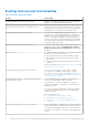
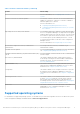
Existing features and functionalities Table 1. Features and functionalities Feature Functionality Configuration Manager distributed environment Support for Configuration Manager, when the configuration manager is set up in a distributed environment. Configure and deploy operating system on Dell’s 11th generation and 12th generation of PowerEdge servers. You can configure Dell’s 11th generation or 12th generation of PowerEdge servers using DLCI through Lifecycle Controller.
Table 1. Features and functionalities (continued) Feature Functionality For more information, see Configuring iDRAC Profiles for a System. Connect to Dell FTP for Firmware updates You can now connect to the FTP site to download firmware updates for a system or collection. You can also schedule a firmware update for a collection. For more information, see: ● Comparing and Updating Firmware Inventory. ● Comparing and Updating Firmware Inventory for Systems in a Collection.
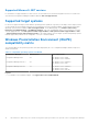
Supported Microsoft .NET versions For information on supported Microsoft .NET versions, see the Dell Lifecycle Controller Integration Version 3.1 for Microsoft System Center Configuration Manager Installation Guide at dell.com/support/home.
2 Use case scenarios This section describes typical use cases and tasks that you can perform with DLCI for Microsoft System Center Configuration Manager (Configuration Manager).
Creating, editing, and saving a RAID profile of a system You can create, edit, and save the RAID profile of a system and apply it when you deploy an operating system to a collection of systems on the Configuration Manager console. Prerequisites ● Common Prerequisites ● RAID controller and firmware that supports Local Key Management Workflow 1. Launch the System Viewer utility on the Configuration Manager console for a particular system. For more information, see System Viewer Utility. 2.
Deploying operating system on collection You can use DLCI for Configuration Manager to deploy an operating system on a collection of systems on the Configuration Manager console. Prerequisites ● Common Prerequisites. ● You must select the Driver Cab which is compatible with the boot image (WinPE version). You can view the DTK README to select the correct version of cab file for specific WinPE or OS architecture, and also can provide the location of the DTK Self-Extracting EXE.
● Administrator privileges on the iDRAC of the target systems. Before you begin Before you begin exporting the system profile for a single system or a collection: ● Make sure that operations such as firmware update, operating system deployment, and firmware configurations are not running.
● User Data is not present in the backup image file. If you overwrite the existing configuration with the backup image file, the user data is not restored. ● During import, operations such as firmware update, operating system deployment, and firmware configurations are not running. ● After you deploy the operating system using Lifecycle controller, the OEMDRV is open for 18 hours.
Working With NIC or CNA Profiles You can configure the different attributes of specific network interface cards (NICs) or converged network adapters (CNAs) embedded in the system and save them to a profile. You can create and edit NIC or CNA profiles using the System Viewer utility. Prerequisites For more information, see Common Prerequisites. Workflow 1. Launch the System Viewer utility on the Configuration Manager console for a particular system. For more information, see System Viewer Utility. 2.
3 Using Dell Lifecycle Controller Integration This chapter discusses the various operations that you can perform after you install DLCI on Configuration Manager. Before you begin using DLCI for Configuration Manager, ensure that the target system is auto-discovered and present in the All Dell Lifecycle Controller Servers collection on the Configuration Manager console.
Dell Deployment ToolKit The Dell Deployment Toolkit (DTK) includes a set of utilities, sample scripts, and sample configuration files that you can use to deploy and configure the Dell systems. You can use DTK to build script-based and RPM-based installation for deploying large number of systems on a pre-operating system environment in a reliable way, without changing their current deployment processes.
Deployment Kit (ADK), depending on the configuration, and all the Windows PE custom install packages are added to the boot image. Use existing Boot Image from Configuration Manager This option allows you to select an existing boot image in Configuration Manager. Select an existing boot image from the drop-down list and use it to create a Dell boot image. Use a custom Boot Image Select this option to import a custom boot image from any other location.
Auto-discovery and handshake The auto-discovery and handshake feature enables the iDRAC on target systems to locate the provisioning service and establish communication with the Site Server. The Dell Provisioning service provisions a management account and updates Configuration Manager with the new system. The Dell Lifecycle Controller Utility (DLCU) for Configuration Manager uses the provisioned account to communicate with the iDRAC of target systems, to invoke the enabled features.
NOTE: If you have downloaded an ISO image, then create a physical disk or mount it on a virtual drive. 3. Select the drive in which you inserted the DVD and click Next. A list of driver packages for a combination of servers and operating systems is displayed. 4. Select the required packages and click Finish. A progress bar displays the status of the import. After the import is complete, the import summary is displayed.
Creating a custom task sequence 1. Launch the Configuration Manager Console. The Configuration Manager Console screen is displayed. 2. In the left pane, select Software Library > Overview > Operating Systems > Task Sequences. 3. Right-click Task Sequences, and then click Create Task Sequence. The Create Task Sequence Wizard is displayed. 4. Select Create a new custom task sequence, and click Next. 5. Enter a name for the task sequence in the Task sequence name text box. 6.
The Select a Driver Package window is displayed. 3. Click DLCI Driver Packages. A list of driver packages available in the Dell Lifecycle Controller Integration is displayed. 4. Select a package for a Dell PowerEdge server, such as Dell PEM630-Microsoft Windows 2012 R2-OM8.1.0. 5. Click Apply. NOTE: After operating system deployment, make sure that the mass-storage driver installed is same as that specified in the Task Sequence. If you find any differences, then update the driver manually.
● Do not modify the existing account - This option is selected by default, clear this option to provide credentials else existing credentials are maintained. Make sure that you enter the valid credentials for iDRAC. You can provide credentials authenticated on the active directory. NOTE: You can enter only specific special characters in the user name field. For more information on the special characters that you can use in the iDRAC user name field, see the iDRAC documentation available at dell.
3. Provide the credentials to login to the iDRAC console and view or edit the details of the iDRAC configuration of the system. You can provide credentials authenticated on the active directory. Launching the integrated Dell Remote Access Controller Console from the Task Viewer To launch the iDRAC console from the Task Viewer: 1. Launch the Task Viewer by clicking the Dell icon on the task bar.
Additional tasks you can perform with Dell Lifecycle Controller Integration Configuring Security To configure security for DLCI, you must: ● Validate a Dell factory-issued Client Certificate on (iDRAC). For more information, see Validating a Dell Factory-Issued Client Certificate on the Integrated Dell Remote Access Controller for Auto-Discovery. ● Pre-authorize systems for auto-discovery. For more information, see Pre-authorizing Systems for Auto-Discovery. ● Change administrative credentials.
Using the Graphical User Interface You can also use the Graphical User Interface (GUI) to change the security configurations. Use the following command to open the GUI screen: C:\Program Files (x86)\Dell\DPS\ProvisionWS\bin\import.exe -DisplayUI NOTE: The DisplayUI term is case sensitive.
About creating Array Builder When you use the RAID profile that you created using Array Builder as part of the operating system deployment of DLCI for Configuration Manager, it detects the existing controller(s) on the server as well as the disks attached to each controller. It then tries to match the physical configuration(s) that the utility detected, to the logical configurations you defined in the configuration rules.
Variable Conditions To provide the ability to use the same RAID configuration in multiple logical configurations, variable evaluation is provided so that a different configuration for arrays and logical drives can be applied to different situations. Variable condition elements contain arrays and global hot spares, and are of two types: ● No variables defined: This is the default configuration inserted with every controller, and cannot be removed or moved from last in the order.
Editing an array To edit an array: 1. Select the array and click Arrays→ Edit Array. The Array Settings window is displayed. You can select a different RAID level for the array. 2. Click OK to apply the changes, or Cancel to return to Array Builder. Deleting an array To delete an array: 1. Select the array and click Arrays→ Delete Array. A message is displayed that all the attached disks will be deleted. 2. Click Yes to delete or No to cancel.
● All Remaining Disks — These disks provide an option to define an array without specifying the exact number of disks. If the controller configuration specifies the number of disks required, an equivalent number of disks are added to the non-RAID group. If the controller specifies the exact quantity, disks cannot be added or removed from the controller – they can only be moved from array to array (or the non-RAID group).
4 Using the Configuration Utility This section describes the various operations that you can perform with the Dell Lifecycle Controller Configuration Utility. You can use the Config Utility from the Configuration Manager console to: ● Create a new Lifecycle Controller boot media to deploy operating systems remotely. For more information, see Creating a Lifecycle Controller Boot Media. ● Configure hardware and deploy the operating system on the target systems in the collection.
2. In the Dell Lifecycle Controller Configuration Utility window, select Create new Lifecycle Controller Boot Media on the left-hand pane. 3. Click Browse and select the bootable ISO that you created. For more information, see Creating a Task Sequence Media Bootable ISO. 4. Specify the folder or path to save the Dell Lifecycle Controller boot media. NOTE: It is recommended to save the boot media to the local drive, and if required copy it to a network location. 5. Click Create.
ESXi installation is supported only on a hard disk for this release. For both ESXi and Red Hat Enterprise Linux, the operating system is installed on the first disk with default configuration. For Red Hat Enterprise Linux the following are set: ● Language is set to US ● Keyboard is set to US (U.S. English) ● By default, Time zone is set to America, New York For deploying the Red Hat Enterprise Linux 6.5 and Red Hat Enterprise Linux 7.
1. In Configuration Manager 2012, or Configuration Manager 2012 SP1, or Configuration Manager 2012 R2, under Device Collections, right-click any appropriate Dell collection and select Dell Lifecycle Controller > Launch Config Utility. 2. From the Dell Lifecycle Controller Configuration Utility, select Hardware Configuration and Operating System Deployment. 3. Select Update Firmware from a Dell Repository if you want to update the Firmware on the collection.
After the deployment is successful, the system with iDRAC moves to the Managed Dell Lifecycle Controller (OS Deployed) collection under All Dell Lifecycle Controller Servers. NOTE: If you change the hostname of the target systems after you deploy the operating system, the system continues to appear under the Managed Dell Lifecycle Controller (OS Deployed) collection on the Configuration Manager console. You do not need to re-discover the system when you change the hostname.
1. Click Browse and select the NIC/CNA profile that you created using the System Viewer utility. This profile is applied during the hardware configuration process. For more information on creating NIC/CNA profiles, see Creating a NIC or CNA Profile. 2. If you select a simple NIC profile you can validate if all the settings in the profile are applied on the target system by launching the Unified Server Configurator on the target system. 3.
Table 4. iDRAC profile settings (continued) S.No Target Server Profile Settings What is Applicable ● All attributes in IPv4 settings. ● Only vLAN ID and vLAN priority attributes from Advanced LAN settings. 3. Rack, Tower, or Blade system with Static IP address IPv4 Configuration attributes only. IPv4 address source is updated. 4. Rack, Tower, or Blade systems LAN Settings attributes only. Applied only to Rack and Tower systems and not to Blade systems. 5.
1. In Configuration Manager 2012 or Configuration Manager 2012 SP1, or Configuration Manager 2012 R2, under Device Collections, right-click All Dell Lifecycle Controller Servers and select Dell Lifecycle Controller > Launch Config Utility. 2. From the left pane of the Dell Lifecycle Controller Configuration Utility, select Firmware Inventory, Compare, and Update. 3. Select a baseline from the following options: ● Dell PDK Catalog — to specify a Dell PDK catalog to compare with the firmware inventory.
Verifying Communication With Lifecycle Controller Use the following steps to verify the credentials of the discovered systems with iDRAC: 1. In Configuration Manager 2012, or Configuration Manager 2012 SP1, or Configuration Manager 2012 R2, under Device Collections, right-click All Dell Lifecycle Controller Servers and select Dell Lifecycle Controller > Launch Config Utility. 2. From the left pane of the Dell Lifecycle Controller Configuration Utility, select Session Credentials, Verify Communication. 3.
1. In the Configuration Manager 2012 or Configuration Manager 2012 SP1, or Configuration Manager 2012 R2, console, select Administration > Site Configuration > Sites > Right-click > Configure Site Components > Out of Band Management. The Out of Band Management Component Properties window is displayed. 2. Click the Dell Lifecycle Controller tab. 3. Under Local User Account on Lifecycle Controllers, click Modify. 4.
Importing the system profiles in a collection You can import the system profiles/backup files that you have created. This option is applicable only if you have created backup images/profiles of the systems in the collection. To launch the Platform Restore screen for a collection: 1.
● Configuration Applied — the configuration is applied to the target system. 5. Select any record on the comparison report and click View Details to view the Port Comparison details. The details of the ports on the system are displayed. The color coding is similar to the Comparison Report screen. See step 4. 6. Select the port and click View Details to view the Personality Comparison details. The following details are displayed: ● Partition — the partition number on the port.
5 Using the Import Server Utility This section describes the various activities that you can perform using the Import Server utility. This utility is installed when you install DLCI for Configuration Manager. For information on installing Dell Lifecycle Controller Integration for Configuration Manager, see the Installation Guide.
The managed server are displayed in green color. 6. Click Next and select the servers that you want to import. By default all systems where the Authentication status is Success, are selected. 7. Click Save As to save the report as a .CSV file in any location. 8. Specify the Target Collection under which you want the imported servers to be displayed and click Next. 9. Click Save As to save the report as a .CSV file in any location. 10. After the import process is complete, click Close to close the utility.
6. Select the variables you want to import. By default, the records with ADD and UPDATE actions on the grid are selected. The records with the DELETE action are not selected. You must select the record if you want to delete it from the system. You can also filter the records on the grid based on the system name. 7. Click Next. 8. Click Save As to save the report as a .CSV file in any location. 9. After the import process is complete, click Close to close the utility.
6 Using the System Viewer Utility This chapter describes the operations that you can perform with the System Viewer Utility. You can use the System Viewer Utility to: ● View and edit the hardware configuration. For more information, see Viewing and Editing BIOS Configuration. ● View and edit the RAID configuration. For more information, see Viewing and Configuring RAID. ● Create and edit iDRAC configuration profiles for your system. For more information, see Configuring iDRAC Profiles for a System.
The BIOS Attributes tab displays the BIOS attributes and current settings of the system. The Boot Sequence tab displays the boot sequence information of the system. 2. In the BIOS Attributes tab, select the attributes to be included in your profile by selecting the check box against each attribute. If you check Select All, all the attributes in the list are selected. NOTE: You can leave the BIOS attributes in a profile unchecked.
2. Click the Boot or UEFI Sequence tab. The current BIOS or UEFI boot sequence and hard disk drive sequence is displayed. 3. Use the Move Up and Move Down to change the BIOS or UEFI boot sequence or the hard disk drive sequence. 4. Click OK to save the changes. NOTE: ● For 13th generation of Dell PowerEdge servers, you can view the BIOS attributes and boot sequence of the currently saved boot mode only. ● Click Reset to reset any changes made.
The Edit User screen is displayed. NOTE: You cannot edit the user account that DLCI uses to access the iDRAC of the system. 7. Specify the following details: ● General Details — Type the user name and password. You must specify the password when you create or edit a user account. ● IPMI LAN user Privilege granted — Select the type of user from the drop-down list to grant the IPMI LAN user privilege.
4. In ● ● ● the Add Adapter dialog box, perform the following: Select the Adapter type from the drop-down list. Select the adapter location and specify the slot number. Click OK. The adapter is now added to the Network Adapter Configuration screen. 5. If you want to remove any of the adapters from the profile, select the adapter and click Remove. 6. Select the adapter and click Configure to configure it. For more information on configuring the adapter, see Configuring Adapters. 7.
Under Personalities and Settings, select the personality against each partition and set the minimum and maximum bandwidth. You can select from one of the following options: ● NIC ● iSCSI ● FCoE NOTE: You can select the personalities only for CNAs and not for NICs. 7. Click Port Settings to configure the NIC and iSCSI parameters. For more information, see Configuring NIC and iSCSI Parameters. 8. Click OK to save the configurations.
The Network Adapter Configuration screen displays the adapters that you have configured in the profile. 5. Select the adapter you want to edit and click Configure. For more information on configuring the adapter, see Configuring Adapters. 6. If you want to remove any of the adapters from the profile, select the adapter and click Remove. 7. You can also click Add to add an adapter to the profile. For more information, see step 4 in Creating a NIC or CNA Profile. 8.
5. You can filter the information based on any of the baseline details, set schedule based on the available options and then click Update to update your system with the latest firmware. ● start now — to start the update. ● start on next reboot — to start the update when the target system reboots. ● schedule update — to set a date and time for the update. If the updates are scheduled in sequence within an hour of each other; then a warning message is displayed.
Table 6. Lifecycle Controller log details (continued) Column Description ID This is the ID associated with an error message. Click the hyperlink to get more information on the error and the recommended action. You can periodically download the latest message registry from the Dell support website available at dell.com/support/manuals. For more information, see Downloading and Updating the Latest Message Registry.
The message registry does not contain detailed information for user defined Logs of type Work notes (for example, WRK001) or Logs with category Other. To download the 11th and 12th generation Message Registry on the system where you have installed DLCI for Configuration Manager: 1. Visit delltechcenter.com/LC. 2. Navigate to Lifecycle Controller 2 (LC2) Home. 3. On the Lifecycle Controller 2 (LC2) page, in the Dell Event / Error Message Reference section, click Dell Message Registry - English (2.1).
● Import a system profile. For more information, see Importing the System Profile. ● Manage profiles. ● Configure Part Replacement properties for a system. For more information, see Configuring Part Replacement Properties for a System. Prerequisites to export or import a system profile You must upgrade the firmware to the following versions: ● ● ● ● iDRAC Firmware for blade systems to version 3.30 or higher. iDRAC Firmware for rack and tower systems to version 1.80 or higher.
The backup file is appended with the hostname of the system and saved in the following format: -. For example, if the prefix you specify is ABC123, and the hostname of the system is ABCDEFG, the backup file is saved as ABC123-ABCDEFG. Click the View previous backup files link to view any previously created backup files prefixes.
6. Click Next. A summary screen is displayed. 7. Click Finish to start the importing the backup file and submit the task to the Task Viewer. You can launch the Task Viewer to view the status of the task. Configuring part replacement properties for a system The Part Replacement feature provides an automatic update of firmware, or configuration, or both of a newly replaced component in a system, to match that of the original part.
7 Troubleshooting This chapter list the issues and steps to troubleshoot them.
Dell auto-discovery network setup specification For information on auto-discovery error messages, descriptions, and response actions, see the Dell Auto-Discovery Network Setup Specification document at delltechcenter.com Troubleshooting the viewing and exporting of Lifecycle Controller logs When you view the Lifecycle Controller logs for a single system or a collection, the grid view could display the following values — -1 in the No. Column, Not Available in the Category, Description, and ID columns.
Issue 3 Issue: The Create Lifecycle Controller Boot Media option may fail if you have not specified local folder locations for the source and destination folders. Resolution: Ensure that the source and destination paths used are local paths. For example, C:\ . Issue 4 Issue: If the iDRAC version is older than the supported versions in any of the target systems, the Boot to vFlash option in the Deploy Operating Systems workflow may fail.
Resolution: The service tag name is case sensitive. Ensure that the service tag name imported through the import.exe utility matches the service tag name in the iDRAC GUI. Issue 10 Issue: During Discovery and Handshake, the DPS.log displays an empty Site code: followed by a cryptography exception.
Issue 16 Issue: The Modular systems cannot use the hostname in the path to the CIFS share but monolithic systems can use the hostname. Resolution: For Modular systems you must specify the IP address of the CIFS share. Issue 17 Issue: When you are updating the systems with the latest firmware, if the Dell Update Packages (DUPS) take longer than 50 minutes to download over a WAN, then the update task may fail.
ESXi or RHEL deployment on Windows systems moves to ESXi or RHEL collection, but not removed from Windows Managed Collection A system with Windows operating system deployed is moved to collection Managed Collection (OS-Deployed). And, when you deploy a non-Windows operating system (ESXi or RHEL) on the system, the system gets into Managed Dell Lifecycle Controller(RHEL) or Managed Dell Lifecycle Controller(ESXi). However, the machine remains in the Managed Collection (OS-Deployed) with the same name.
8 Related documentation and resources For more information on Configuration Manager such as installation, features, and functionalities, see the Microsoft TechNet site at technet.microsoft.com. In addition to this guide, you can access the following guides available at dell.com/support/manuals. On the Manuals page, click Software and Security > System Management.
○ ○ ○ ○ Remote Enterprise Systems Management Serviceability Tools Client Systems Management Connections Client Systems Management 4. To view a document, click the required product version. ● Using search engines: ○ Type the name and version of the document in the search box.